Environmental protection dust remover

A dust removal device and environmental protection technology, applied in the direction of dust removal, bendable lead wire device, photovoltaic power generation, etc., can solve the problems of deteriorating environment and air, damage to power supply lines, short power supply lines, etc., to improve power supply safety and service life , Prevent accidental electric shock accidents, reduce the effect of workers' labor

Inactive Publication Date: 2017-08-18
GUANGZHOU QIUDAI TRADE CO LTD
View PDF2 Cites 2 Cited by
  • Summary
  • Abstract
  • Description
  • Claims
  • Application Information

AI Technical Summary

Problems solved by technology

[0002] With the development of the industrial age, people's awareness of environmental protection is increasing. In the production of industrial products, a large amount of dust is generated. Without proper dust removal measures, the environment and air in the workshop will be polluted and deteriorated, which will be harmful to the human body. The health of the dust removal equipment is generally used for industrial dust removal. However, due to the strong mobility of the dust removal equipment during the dust removal operation, the power supply line of the existing dust removal equipment is relatively short, and it is difficult to meet the power supply when moving. Needed, when encountering similar phenomena, one or more terminal boards are generally used to extend the connection to ac

Method used


Image

  • Environmental protection dust remover
  • Environmental protection dust remover
  • Environmental protection dust remover

Examples


Embodiment Construction

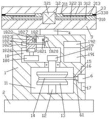
[0022] Such as Figure 1-Figure 4 As shown, an environmental protection dust removal device of the present invention includes a container 1 fixed on the top of the base body 2 and a frame 3 arranged above the container 1, and an empty chamber 11 is provided in the container 1, and the empty chamber 11. The container 1 at the top is provided with a first installation groove 18 and a second installation groove 19. The inner top wall of the first installation groove 18 is provided with a chute 182. The outer wall of the container 1 is provided with a side opening 17, and a communication hole 15 and a card slot 16 are provided between the opening side slot 17 and the empty compartment 11, and a steering shaft extending up and down is provided inside the empty compartment 11. 12. The top extension section of the steering shaft 12 passes through the inner wall of the container 1 and penetrates into the first installation groove 18, and the tip of the steering shaft 12 in the first i...


PUM


Abstract

The invention discloses an environmental protection dust remover comprising a container fixed to the top of a base, and a rack arranged above the container. The container is internally provided with an empty bin, and a first mounting groove and a second mounting groove are arranged in the container on the top of the empty bin, and the inner roof of the first mounting groove is provided with a sliding chute; the outer wall of the container at the right side of the empty bin is internally provided with a flash groove, and a through hole and a slot are formed at the part between the flash groove and the empty bin which is internally provided with a steering shaft arranged and stretched up and down; the top extension section of the steering shaft penetrates through the inner wall of the container and extends into the first mounting groove, and the end of the steering shaft in the first mounting groove is provided with a first fluted disc; the steering shaft in the empty bin is fixedly provided with a steering wheel, and cables are winded around an inner ring of the steering wheel; and the sliding chute is internally provided with a sliding block of which the bottom penetrates into the first mounting groove, and the bottom end surface of the sliding block is internally provided with a first motor. The environmental protection dust remover disclosed by the invention has the advantages of simple structure, easy operation and high safety, and is capable of winding up the cables automatically.

Description

technical field [0001] The invention relates to the technical field of environmental protection dust removal, in particular to an environmental protection dust removal device. Background technique [0002] With the development of the industrial age, people's awareness of environmental protection is increasing. In the production of industrial products, a large amount of dust is generated. Without proper dust removal measures, the environment and air in the workshop will be polluted and deteriorated, which will be harmful to the human body. The health of the dust removal equipment is generally used for industrial dust removal. However, due to the strong mobility of the dust removal equipment during the dust removal operation, the power supply line of the existing dust removal equipment is relatively short, and it is difficult to meet the power supply when moving. Needed, when encountering similar phenomena, one or more terminal boards are generally used to extend the connectio...

Claims


Application Information

Patent Timeline
IPC IPC(8): B08B15/00H01R13/72H02S40/10H02S30/20B08B1/02
CPCB08B1/002B08B1/02B08B15/00H01R13/72H02S30/20H02S40/10Y02B10/10Y02E10/50
Inventor 李彬
Owner GUANGZHOU QIUDAI TRADE CO LTD
Why Eureka
Try Eureka