Lagging mechanism for drawing die and application method

A drawing die and hysteresis technology, which is applied in the field of hysteresis mechanism for drawing dies, can solve problems such as increased stamping costs, additional costs, and crushed parts, and achieves the effects of simple structure, reduced stamping costs, and resource saving

Inactive Publication Date: 2017-08-18
烟台泰利汽车模具股份有限公司
View PDF6 Cites 4 Cited by
  • Summary
  • Abstract
  • Description
  • Claims
  • Application Information

AI Technical Summary

Problems solved by technology

The actual reality is that the air cushion of the mechanical press used in many stamping factories does not have a delay function. The use of the drawing die with the binder body on the upper die is limited, and the pressed and formed parts are often crushed. Unable to produce qualified products
[0003] Although the existing pressing body is arranged on the drawing die, the place that is easy to wrinkle can be preformed in place at the initial stage of drawing, and the problem of wrinkling of the part when the existing stamping part is solved, but the pressing body belt A new technical problem arises: if the press used does not involve the function of jacking up and delaying, the pressed and formed parts will often be crushed again, so it is necessary to purchase a new press and the press must have a jacking up delay function. If there is no time function, it will lead to additional costs and increase the cost of stamping, which is not conducive to solving the problem of wrinkling of parts

Method used


Image

  • Lagging mechanism for drawing die and application method
  • Lagging mechanism for drawing die and application method
  • Lagging mechanism for drawing die and application method

Examples


Embodiment Construction

[0044] The principles and features of the present invention are described below in conjunction with examples, which are only used to explain the present invention and are not intended to limit the scope of the present invention.

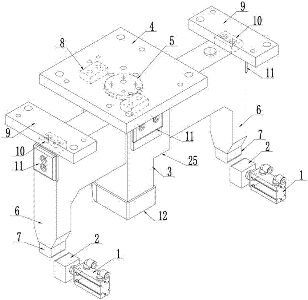
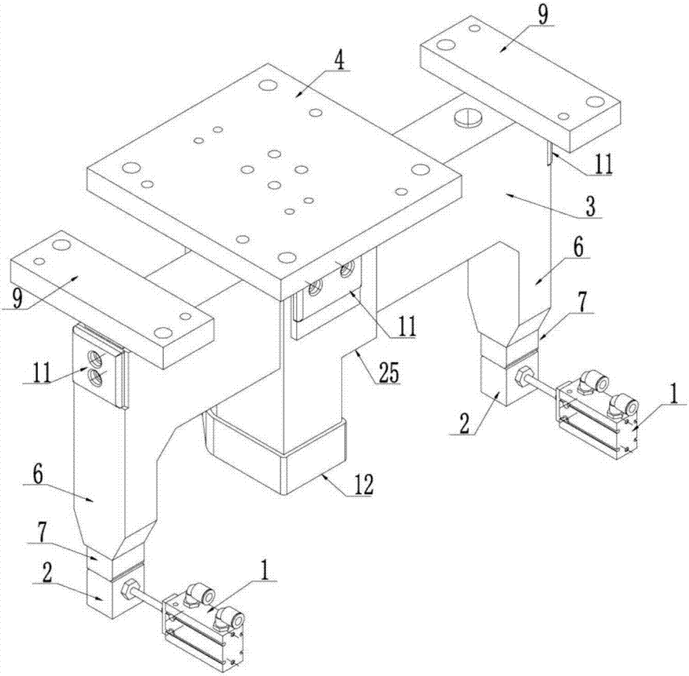
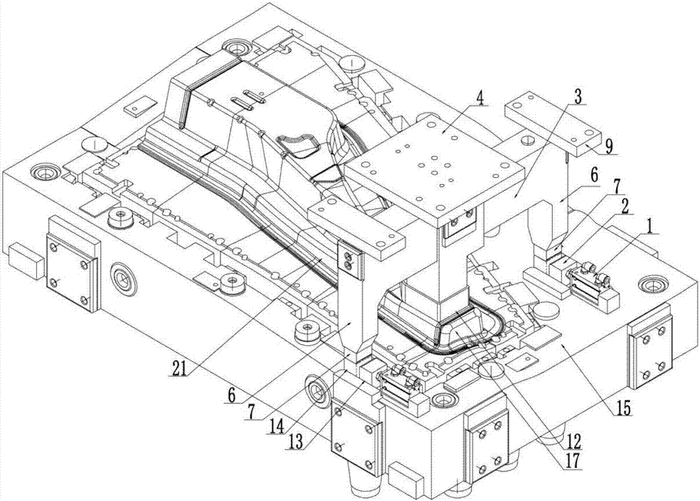
[0045] Such as Figure 1-Figure 6 As shown, a hysteresis mechanism for a drawing die includes two groups of symmetrically arranged hysteresis cylinders 1 and hysteresis pads 2, the hysteresis pads are connected with the piston rods of the hysteresis cylinders, and the cylinder body of the hysteresis cylinders is installed On the blankholder 15, the blankholder is installed on the lower die 17 of the drawing die, and the drawing die also includes an upper die 16 matched with the lower die, and the upper die is provided with a press The material body 3 is provided with a limit cover plate 4 on the upper die above the binder body, and a nitrogen cylinder 5 is arranged on the limit cover plate, and the ejector rod of the nitrogen cylinder presses against...


PUM


Abstract

The invention discloses a hysteresis mechanism for a drawing die and an application method thereof. The hysteresis mechanism includes a hysteresis cylinder and a hysteresis cushion block, the hysteresis cushion block is connected with the piston rod of the hysteresis cylinder, the hysteresis cylinder is mounted on a blank holder, and the blank holder is installed On the lower die, the drawing die also includes an upper die, the upper die is provided with a binder body, a limit cover plate is arranged above the binder body, a nitrogen cylinder is arranged on the limit cover plate, and the ejector rod of the nitrogen cylinder and the binder body The height of the contact and hysteresis pads is the same as the movement stroke of the binder body; the application method of the hysteresis mechanism: 1. Place the sheet; 2. Clamp the mold and stamp the sheet into a finished product; 3. Start the hysteresis mechanism; 4. Delay the mold opening press body Exit; 5. Take out the stamping part. In the process of mold opening, the binder body starts to withdraw after the end of the binder ring stroke, so that the binder ring and the binder body move first and then later, avoiding the two moving at the same time and damaging the stamping part, and it can be used without air cushion The delay function is used on the press to save resources and reduce stamping costs.

Description

technical field [0001] The invention relates to a hysteresis mechanism for a drawing die and an application method thereof, belonging to the technical field of cold stamping drawing dies. Background technique [0002] In stamping industries such as automobiles and home appliances, there is a shape of a part in the length direction, with high and low platforms on the top surface, or a concave shape in the middle, such as Figure 7 As shown, the top surface of the product is uneven, the height gap is large, and there are high and low platforms. During the drawing and forming process of this kind of product 21, there will generally be many materials and wrinkles on the low top surface 26, which will affect the parts. Quality, even serious wrinkling, parts are scrapped, in order to solve the drawing wrinkling of such parts and prevent the parts from drawing wrinkling on the low top surface, it is generally necessary to set the upper pressing on the drawing die at the correspondin...

Claims


Application Information

Patent Timeline
Patent Type & Authority Applications(China)
IPC IPC(8): B21D37/10B21D22/22
CPCB21D37/10B21D22/22
Inventor 孙华强林磊陈昔润李英章曹洪花
Owner 烟台泰利汽车模具股份有限公司
Why Eureka
Try Eureka