Multifunctional precision sliding table saw for laboratory and using method thereof

A multi-functional, push table saw technology, used in circular saws, sawing equipment, metal processing and other directions, can solve the problem that push table saws cannot meet the requirements of rapid size measurement and accurate cutting safety, etc., to improve operational safety and simplify Operation steps, the effect of simple operation steps

Active Publication Date: 2017-08-18
NORTHEAST FORESTRY UNIVERSITY
View PDF5 Cites 2 Cited by
  • Summary
  • Abstract
  • Description
  • Claims
  • Application Information

AI Technical Summary

Problems solved by technology

[0005] The present invention aims to solve the problem that the existing sliding table saw cannot meet the requirements of fast measurement, precise cutting and safety of the size, thus providing a laboratory multifunctional precision sliding table saw and its use method

Method used


Image

  • Multifunctional precision sliding table saw for laboratory and using method thereof
  • Multifunctional precision sliding table saw for laboratory and using method thereof
  • Multifunctional precision sliding table saw for laboratory and using method thereof

Examples


specific Embodiment approach 1

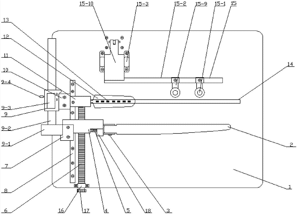
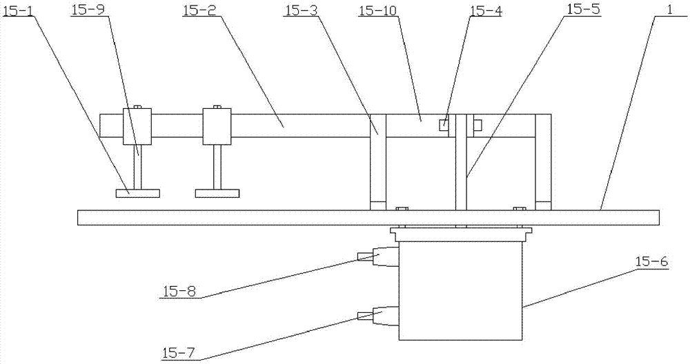
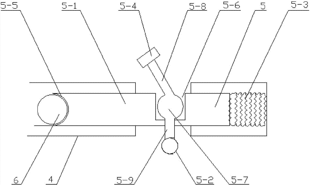
[0045] Specific implementation mode one: combine Figures 1 to 3 , this embodiment is a laboratory multifunctional precision sliding table saw consisting of a workbench 1, a ruler 2, a rotating nut 3, a first fixing frame 4, a buckle wrench 5, a guide screw 6, a first fixing block 7, and a fixing rod 8 , electronic display caliper 9, second fixing block 10, second fixing frame 11, knife saw casing 12, pneumatic pressing device 15, third fixing frame 16, guide nut 17, third fixing frame 18 and table saw box ;

[0046] The workbench 1 upper surface is provided with fixed rod 8, is fixedly provided with the second fixed mount 11 on the fixed rod 8, is provided with the first fixed mount 4 slidingly on the fixed rod 8, the left side of the second fixed mount 11 and the first fixed mount 4 There is an electronic display caliper 9 on the side;

[0047] And electronic display caliper 9 is positioned at workbench 1 side edge, and described electronic display caliper 9 is made up of ...

specific Embodiment approach 2

[0062] Embodiment 2: The difference between this embodiment and Embodiment 1 is that the electronic display caliper 9 is an electronic vernier caliper. Others are the same as in the first embodiment.

specific Embodiment approach 3

[0063] Embodiment 3: The difference between this embodiment and Embodiment 1 or 2 is that a counterweight is provided inside the workbench 1 . Others are the same as in the first or second embodiment.

[0064] The advantage of this specific embodiment: there is a counterweight inside the workbench 1 , and the workbench 1 can be automatically restored after being pushed away from the workbench 1 each time. This automatic design further reflects the rationality of the design.


PUM


Abstract

The invention discloses a multifunctional precision sliding table saw for a laboratory and a using method of the multifunctional precision sliding table saw. The problem that an existing sliding table saw cannot achieve rapid size measurement, precision cutting and safety is solved. The multifunctional precision sliding table saw for the laboratory is composed of a workbench, a guiding rule, a rotary nut, a first fixing frame, a buckle spanner, a guide screw rod, a first fixing block, a fixing rod, an electronic digital display caliper, a second fixing block, a second fixing frame, a knife saw shell, a pneumatic compression device, a third fixing frame, a guide nut, a third fixing frame and a sliding table saw box body. The using method comprises the steps that 1, a contour to be cut is drawn on a plate at first; 2, the contour line on one side of the plate overlaps with a circular saw web and is laid; 3, the pneumatic compression device is started, the buckle spanner is moved away, the guiding rule moves along the guide screw rod to the edge of the plate, and then the guide nut is rotated to enable the guiding rule to be tightly attached to the plate; 4, the rotating speed of the circular saw web is adjusted; and 5, the workbench is pushed to move along a sliding groove to cut the plate.

Description

technical field [0001] The present invention relates to a sliding table saw and method of use thereof. Background technique [0002] Sliding table saw is a kind of cutting tool, which is generally composed of frame, fixed table, sliding table and saw blade mechanism. When in use, the sample is usually placed on the sliding table and pushed to the rotating saw blade mechanism to Realize the cutting operation. [0003] However, due to reasons such as unsuitable backing and loose fixation, the sample is prone to displacement during the cutting process, which affects the cutting accuracy. The cutting accuracy is only ±4mm, and the scrap rate is high. On the other hand, the operator often directly pushes the sample by hand. Cutting, while the saw blades of the sliding table saw are directly exposed outside, it is easy to cut the operator's hand during the sample cutting process, resulting in safety accidents. [0004] Compared with the traditional table saw, the laboratory tabl...

Claims


Application Information

Patent Timeline
Patent Type & Authority Applications(China)
IPC IPC(8): B27B5/29B27B5/22B27G3/00B27G19/02B26D1/15B26D5/40B26D7/18B26D7/02
CPCB26D1/15B26D5/40B26D7/02B26D7/18B27B5/222B27B5/29B27G3/00B27G19/02
Inventor 宋永明王发扬
Owner NORTHEAST FORESTRY UNIVERSITY
Why Eureka
Try Eureka