A vacuum vulcanizer for shoemaking

A vulcanizing machine and vacuum technology, which is applied to insoles, shoe uppers, footwear, etc., can solve the problems of vulcanizing machines occupying a large space, not meeting energy-saving requirements, and high site costs, etc., achieving reduced space, short time, and good results Effect

Active Publication Date: 2019-06-18
佛山市誉泰机械自动化科技有限公司
View PDF4 Cites 0 Cited by
  • Summary
  • Abstract
  • Description
  • Claims
  • Application Information

AI Technical Summary

Problems solved by technology

[0002] In the process of shoemaking, the vamp is shaped by the shoe last. In the prior art, the vulcanizer is generally used to complete the vulcanizer. The vulcanizer includes a heating device and a steam device arranged in a straight line. And vacuuming device, etc., through the vacuuming device to make the upper more close to the shoe last, but this kind of vulcanizing machine takes up a lot of space, which does not meet the current requirements of high site costs
[0003] In order to solve the above problems, the existing processing has disclosed a utility model patent with the announcement number CN202241722 and the name "overhead vacuum vulcanization setting machine". According to the description and the attached drawings, the closed chain of the material hanging basket in this patent It is a circle in the vertical plane. At this time, the material hanging basket needs at least a distance of the height of the hanging basket to realize the corner during the corner turning process, that is, a larger distance needs to be set between the hanging baskets. At this time, the same The number of shoes heated by the space and vacuum processed is limited less, otherwise a larger heating space is required for heating. At this time, heating a large space requires more energy, which does not meet the energy-saving requirements

Method used


Image

  • A vacuum vulcanizer for shoemaking
  • A vacuum vulcanizer for shoemaking
  • A vacuum vulcanizer for shoemaking

Examples


Embodiment approach

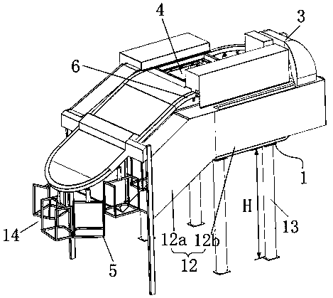
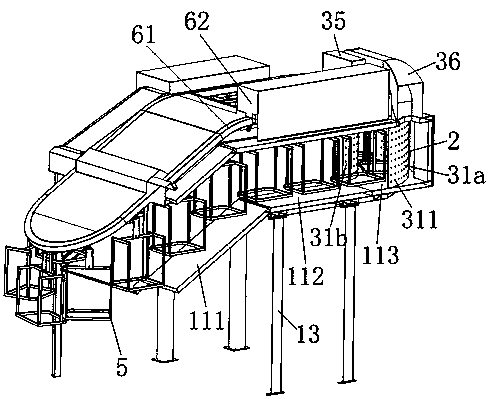
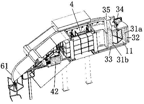
[0050] In the first embodiment, the drying tunnel 11 includes an inclined drying tunnel 111, a horizontal drying tunnel 112 and an arc-shaped drying tunnel 113 arranged in sequence along the moving direction of the conveying chain ring 61, and the inclined drying tunnel 111 is arranged at the left oblique straight part Or at the right oblique straight part, the arc-shaped drying tunnel 113 is arranged at the horizontal arc-shaped transition part 611;

[0051] In the second embodiment, the drying tunnel 11 includes a horizontal drying tunnel 112 and an arc-shaped drying tunnel 113 arranged in sequence along the moving direction of the conveying chain ring 61 , and the arc-shaped drying tunnel 113 is arranged at the horizontal arc-shaped transition portion 611 .

[0052] That is to say, it is preferable to set both the straight section and the horizontal arc-shaped transition portion 611 as the drying tunnel 11. At this time, the drying tunnel 11 has a large space and can fully h...


PUM

PropertyMeasurementUnit
heightaaaaaaaaaa

Abstract

The invention discloses a vacuum vulcanizing machine for shoemaking. The vacuum vulcanizing machine comprises a rack, a heating system, a circulating air system, a vacuum pumping system, a shoe rack for conveying shoes, and a conveying system for moving the shoe rack. The conveying system comprises a conveying chain ring and a driving device for driving the conveying chain ring to cyclically move. The conveying chain ring comprises a bent oblique chain and a horizontally bent horizontal chain. The oblique chain is arranged outwards and obliquely towards the oblique lower position from one end of the horizontal chain. The vacuum pumping system is arranged on the left side or the right side of the conveying chain ring, and comprises a vacuum pump, a left side cover and a right side cover. The left side cover and the right side cover are arranged on the two sides of the conveying chain ring on the corresponding side. The left side cover and the right side cover can reciprocate in the width direction of the conveying chain ring. A drying channel for containing the shoe rack is arranged at the position, below part of the conveying chain ring, of the rack, at least part of the drying channel is arranged at the positions, on the opposite sides of the left side cover and the right side cover, of the conveying chain ring, the heating system is used for heating vamps in the drying channel, and the circulating air system is used for supplying circulating air into the drying channel. The vacuum vulcanizing machine is low in energy consumption and high in space utilization rate.

Description

technical field [0001] The invention relates to the technical field of shoemaking equipment, in particular to a vacuum vulcanizer for shoemaking. Background technique [0002] In the process of shoemaking, the vamp is shaped by the shoe last. In the prior art, the vulcanizer is generally used to complete the vulcanizer. The vulcanizer includes a heating device and a steam device arranged in a straight line. And vacuuming device etc., make vamp more close to shoe tree by vacuuming device, but this kind of vulcanizing machine takes up a large space, does not meet the requirement of high site cost now. [0003] In order to solve the above problems, the existing processing has disclosed a utility model patent with the announcement number CN202241722 and the name "overhead vacuum vulcanization setting machine". According to the description and the attached drawings, the closed chain of the material hanging basket in this patent It is a circle in the vertical plane. At this time,...

Claims


Application Information

Patent Timeline
Patent Type & Authority Patents(China)
IPC IPC(8): B29C35/02A43D11/12
CPCA43D11/12B29C35/0277
Inventor 梁起彬
Owner 佛山市誉泰机械自动化科技有限公司
Why Eureka
Try Eureka