Novel electrolysis device

A technology of electrolysis device and power receiving device, which is applied in the direction of electrolysis process, electrolysis components, electrodes, etc. It can solve the problems of affecting the life of the anode, affecting the efficiency of electrolysis, and the peeling off of the anode coating, and achieves simplified pipeline layout, simple operation, The effect of reducing the footprint of the device

Inactive Publication Date: 2017-08-18
王兆兵
View PDF9 Cites 0 Cited by
  • Summary
  • Abstract
  • Description
  • Claims
  • Application Information

AI Technical Summary

Problems solved by technology

The current problem is that the cathode plate will deposit dirt during the electrolysis process, and it is necessary to periodically interrupt the electrolysis and switch to the descaling program. The current descaling methods include: pickling and dissolution method and reverse current method. After the cathode scaling is removed , and then turn to normal electrolysis, the disadvantages of these two methods are:
[0003] The pickling method will corrode the electrode and affect the life of the electrode. The pickling is not easy to complete, and the residual scale will also affect the electrolysis efficiency.
[0004] The reverse current method will cause the anode to undergo a reduction reaction, and the anodic oxide coating will partially generate metal products after receiving electrons. At the same time, the hydrogen evolution reaction will cause hydrogen permeation, which will cause the anode coating to fall off, seriously affecting the life of the anode, and has not been widely used. Promote application

Method used


Image

  • Novel electrolysis device
  • Novel electrolysis device
  • Novel electrolysis device

Examples


Embodiment Construction

[0026] Below in conjunction with accompanying drawing, the present invention is described in detail.

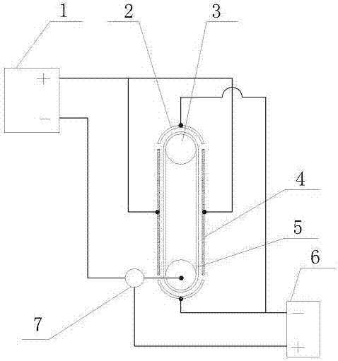
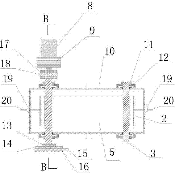
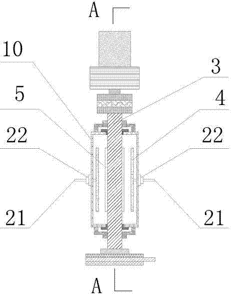
[0027] Such as figure 1 , figure 2 , image 3 A new type of electrolysis device shown mainly includes a tank body 10, a rotating device, a rotating power receiving device, an electrolysis power supply 1, and an inverted pole power supply 6. There is a cathode cylinder 3 at both ends of the tank body 10. A cathode roller 3 is covered with a cathode plate belt 5, the cathode plate belt 5 is connected end to end to form a closed ring belt and is tensioned by two cathode rollers 3, and the two sides of the cathode plate belt 5 are parallel with the anode plate 4, The anode conductive strip 21 connected to the anode plate 4 extends out of the tank body 10 through the seal 22 and is connected to the positive pole of the electrolysis power supply 1, and the two ends of the two cathode cylinders 3 extend out of the tank body 10 through the shaft seal 12 and are connected to the be...


PUM


Abstract

The invention discloses a novel electrolysis device. The novel electrolysis device mainly comprises a tank body, a rotating device, a rotating powered device, an electrolysis power source and a polarity changing power source, wherein one cathode roller is arranged at each of the two ends in the tank body; a cathode plate strip sleeves the two cathode rollers; anode plates are parallelly placed on the side surfaces of the cathode plate strip; anode conductive bars connected with the anode plates are connected with the anode of the electrolysis power source; the two ends of one of the two cathode rollers are separately connected with the rotating device and the rotating powered device; the rotating powered device is connected with the cathode of the electrolysis power source, is connected with the anode of the polarity changing power source, and is provided with a change-over switch used for switching a current loop; and polarity changing semicircular arc plates connected with the cathode of the polarity changing power source are arranged on the outer edges of the cathode rollers. The novel electrolysis device has the advantages that automatic cleaning is achieved, the cathodes do not scale, electrolytic efficiency is high, pickling facilities are not required, damage of pickling to the polar plates is eliminated, the anodes are not subjected to polarity changing, and service life of the anode plates is prolonged.

Description

technical field [0001] The invention relates to water treatment equipment, in particular to electrolytic chlorine production disinfection equipment. Background technique [0002] On-site sodium hypochlorite generators are widely used to produce sodium hypochlorite because of their safety, stability and reliability. The device has a high degree of automation and realizes unattended operation. The current problem is that the cathode plate will deposit dirt during the electrolysis process, and it is necessary to periodically interrupt the electrolysis and switch to the descaling program. The current descaling methods include: pickling and dissolution method and reverse current method. After the cathode scaling is removed , and then turn to normal electrolysis, the disadvantages of these two methods are: [0003] The pickling method will corrode the electrode and affect the life of the electrode. The pickling is not easy to complete, and the residual scale will also affect the ...

Claims


Application Information

Patent Timeline
IPC IPC(8): C25B1/26C25B11/04C25B11/02C25B9/12
CPCC25B1/265C25B11/02C25B11/04C25B9/30C25B11/034
Inventor 王兆兵姚发艳
Owner 王兆兵
Why Eureka
Try Eureka