Rectangular steel pipe confined concrete column joint without stirrups and construction method thereof

A technology for constraining concrete and rectangular steel pipes, which is applied to buildings and building structures, etc., can solve problems such as failure to meet the seismic design requirements of strong joints and weak members, and joint weakening, and achieve reliable joint performance, prevent instability, and simplify the construction process. Effect

Inactive Publication Date: 2017-08-18
CHONGQING UNIV
View PDF9 Cites 2 Cited by
  • Summary
  • Abstract
  • Description
  • Claims
  • Application Information

AI Technical Summary

Problems solved by technology

[0003] However, the joint form of the steel tube-confined concrete column frame that has been applied so far cannot meet the seismic design requirements of strong joints and weak members because the steel tubes are disconnected in the joint area, which weakens the joints.

Method used


Image

  • Rectangular steel pipe confined concrete column joint without stirrups and construction method thereof
  • Rectangular steel pipe confined concrete column joint without stirrups and construction method thereof
  • Rectangular steel pipe confined concrete column joint without stirrups and construction method thereof

Examples


Embodiment 1

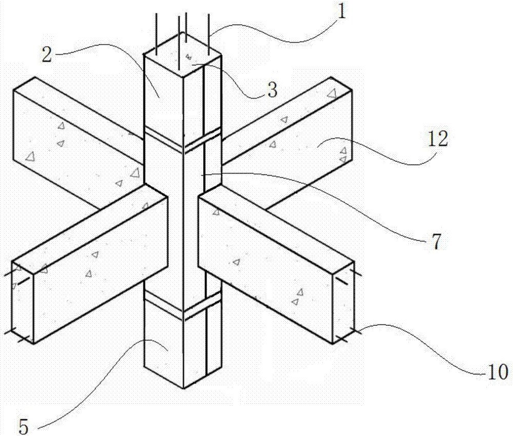
[0056] This embodiment discloses a rectangular steel pipe bound concrete column-reinforced concrete beam partly through joint without stirrups, including an upper column steel pipe 2, a lower column steel pipe 5, a node steel pipe 7, and a reinforced concrete beam.

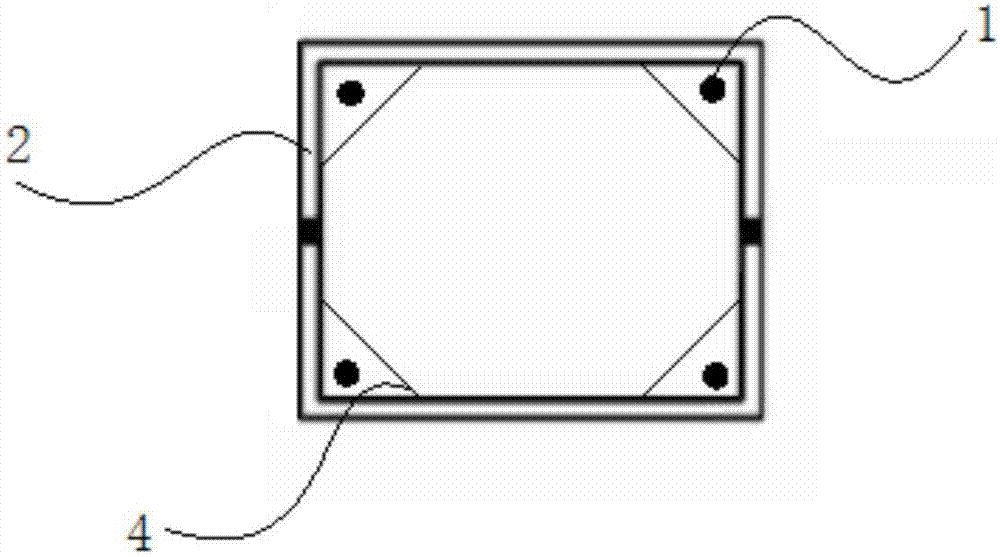
[0057] see figure 1 , image 3 and Figure 5 , the upper column steel pipe 2, the lower column steel pipe 5 and the node steel pipe 7 are all composed of two cold-formed thin-walled channel steels buckled and welded together.

[0058] see image 3 , the four inner corners of the upper column steel pipe 2 are welded with oblique-stayed stiffeners I4. The cable-stayed stiffener I4 vertically penetrates into the steel pipe 2 of the upper column. Each cable-stayed stiffener I4 is connected between two adjacent sides of the upper column steel pipe 2 through a fillet weld.

[0059] see figure 2 and Figure 4 , multiple groups of holes 701 are evenly opened on the node steel pipe 7 for the reinforced concrete bea...

Embodiment 2

[0066] This embodiment discloses a rectangular steel tube-constrained concrete column node without stirrups, including an upper column steel tube 2, a lower column steel tube 5, a node steel tube 7, and a reinforced concrete beam.

[0067] The upper column steel pipe 2, the lower column steel pipe 5 and the node steel pipe 7 are all composed of two cold-formed thin-walled channel steels buckled and welded together.

[0068] see Figure 6 and Figure 7 , the four inner corners of the upper column steel pipe 2 are welded with oblique-stayed stiffeners I4. The cable-stayed stiffener I4 vertically penetrates into the steel pipe 2 of the upper column. Each cable-stayed stiffener I4 is provided with five exhaust holes I401. Each cable-stayed stiffener I4 is connected between two adjacent sides of the upper column steel pipe 2 through a fillet weld. The cable-stayed stiffener I4 and the inner corner of the upper column steel pipe 2 form a hollow triangular prism A with both upper...

Embodiment 3

[0076] This embodiment discloses a construction method for a rectangular steel pipe-confined concrete column without stirrups described in Embodiment 1, which includes the following steps:

[0077] 1) Process the upper column steel pipe 2, the node steel pipe 7 and the lower column steel pipe 5 according to the design requirements:

[0078] Two pieces of cold-formed channel steel are selected, and four obliquely-stayed stiffeners I4 are respectively welded to each inner corner of the cold-formed channel steel through fillet welds. The two pieces of cold-formed channel steel are buckled and welded together with a penetration weld to form the upper column steel pipe 2 . Among them, the upper column steel pipe 2 and the cable-stayed stiffener I4 together constitute the upper column steel pipe complex.

[0079] Two pieces of cold-formed channel steel are selected, and four oblique-stayed stiffeners III6 are respectively welded to the inner corners of the two pieces of cold-formed...


PUM


Abstract

The invention provides a rectangular steel pipe confined concrete column joint without stirrups and a construction method thereof. The beam column joint comprises an upper column steel pipe, a lower column steel pipe, a joint steel pipe and reinforced concrete beams. The upper column steel pipe, the lower column steel pipe and the joint steel pipe are each composed of two pieces of cold-formed thin-walled groove-shaped steel which are buckled and welded together. The construction method of the structure comprises the steps of steel pipe machining, hoisting and welding, rib cage binding, concrete pouring and the like. Large diameter longitudinal ribs are restrained through stiffening ribs at the corners of the steel pipes, so that the column stirrups cannot be arranged while the number of the column longitudinal ribs is decreased, and construction is convenient and quick; partition plates with openings are adopted in the joint area, penetrating of the beam longitudinal ribs can be achieved, and column longitudinal rib positioning and concrete pouring are convenient; and meanwhile the inner partition plates can effectively strengthen a square steel pipe, joint force transmission is direct, performance is reliable, and convenience is provided for assembly type achieving.

Description

technical field [0001] The invention relates to building structural components, in particular to a beam-column frame node of a steel-concrete composite structure. Background technique [0002] Confined steel tube concrete column is a composite vertical load-bearing member formed by pouring concrete in steel tubes. It is a new composite structural component proposed on the basis of steel tube concrete columns to solve the problem of complex structure of the frame joints. The steel pipes of the steel pipe-confined concrete columns are only arranged on the column body, disconnected at the beam-column joints, and combined with the reinforced concrete beams to form the reinforced concrete frame joints. At present, steel pipe confined concrete columns have been used in high-rise buildings, industrial plants and large-span space structures with large load-bearing columns. [0003] However, the currently applied steel-tube-confined concrete column frame joint form cannot meet the s...

Claims


Application Information

Patent Timeline
Patent Type & Authority Applications(China)
IPC IPC(8): E04B1/18E04B1/58
CPCE04B1/18E04B1/58
Inventor 甘丹周绪红刘界鹏李江周政
Owner CHONGQING UNIV
Why Eureka
Try Eureka