Antitheft multifunctional safety box

A safe and multi-functional technology, applied in the field of safes, can solve the problems of lack of alarm equipment and other problems, so as to avoid property loss, prevent deformation of door pins, and increase the use of space

Inactive Publication Date: 2017-08-18
ZHEJIANG OCEAN UNIV
View PDF10 Cites 10 Cited by
  • Summary
  • Abstract
  • Description
  • Claims
  • Application Information

AI Technical Summary

Problems solved by technology

Therefore, this invention can effectively avoid the property loss caused by forgetting to turn the handle when closing the door, but the ...

Method used


Image

  • Antitheft multifunctional safety box
  • Antitheft multifunctional safety box
  • Antitheft multifunctional safety box

Examples


Embodiment 1

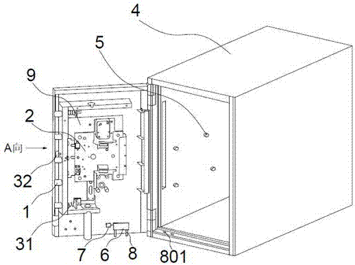
[0025] Such as Figure 1-7As shown, a kind of anti-theft multifunctional safe comprises a cabinet body 4, a cabinet door 9 connected with the cabinet body 4, a moisture-proof chamber 402 is arranged in each cabinet panel of the cabinet body 4, and the cross-section of the moisture-proof chamber 402 is rectangular on one side and It is concave, with a diaphragm in the middle, and a moisture-proof agent is installed in the rectangular cross-section. The two sides of the inner wall of the cabinet body 4 are provided with symmetrical and evenly distributed clamping columns 5. A partition can be placed on the upper end of the clamping column 5 to divide the safe into two parts. Multiple spaces increase the utilization space of the safe, which is conducive to improving the economic value of the safe. A round table is arranged in the middle of the card column 5, and a rubber rubber with a slope is provided on the cylindrical surface of the part of the card column 5 that is in contact ...

Embodiment 2

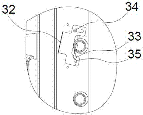
[0029] When the anti-theft multifunctional safe of the present invention is actually working: when opening the door, insert the key into the safe and unlock it, turn the handle counterclockwise, the door latch mechanism 2 will drive the door pin 1 to move, the return spring 31 is compressed, the torsion spring 33 resets, and the brake 32 rotates around the first positioning pin 34 under the action of the torsion spring 33, and reaches the limit position of the arc-shaped limiting groove, that is, it is limited by the second positioning pin 35. At this time, the door pin 1 is blocked by the brake 32, and the mechanical unlocking is completed. , and then manually input the electronic lock password, the electronic lock controller 6 controls the telescopic rod 8 to shorten and break away from the positioning hole 801, and completes the unblanking of the mechanical lock and the electronic lock, and the safe door is in an open state.

[0030] When closing the door, you only need to p...


PUM


Abstract

The invention provides an antitheft multifunctional safety box and belongs to the technical field of safety boxes. The safety box comprises a box body, and a box door connected with the box body. A door catch mechanism is arranged on the inner wall of the box door and is connected with a door bolt. A door bolt automatic reset mechanism is arranged between a door frame and the door catch mechanism and comprises a brake and a reset spring. The reset spring is connected with the door bolt and the door catch mechanism in a buckled mode. The brake is installed on the box door through a first locating pin and a second locating pin. The periphery of the first locating pin is sleeved with a torsional spring. The brake is arranged on one side of the door bolt. An electric lock controller is arranged below the inner wall of the box door. A vibration sensor is connected to one side of the electric lock controller. A telescopic rod is connected to the lower portion of the electric lock controller. The bottom face of the box body is provided with a locating hole corresponding to the telescopic rod. Through the safety box, a thief can be prevented from damaging a protective structure of a mechanical lock, the safety box is opened and closed through a double-lock structure achieved by combining a mechanical lock and an electric lock, and a dampproof function is further achieved.

Description

technical field [0001] The invention relates to the technical field of safes, in particular to an anti-theft multifunctional safe. Background technique [0002] In the prior art, commonly used safe doors are generally not equipped with an automatic door pin reset mechanism. Therefore, when the safe door is closed, the handle needs to be turned, otherwise the door cannot be closed; and people often forget to turn the handle when closing the door, so the safety The cabinet door is still open, which can easily cause property damage. Moreover, most of the anti-theft devices of existing safes are mechanical structures, and the anti-theft devices mainly include mechanical locks and mechanical combination locks. Alarm sound, the crime method used by thieves is often to destroy the combination lock first. For example, using an electric drill to destroy the alarm in the cabinet door and then using tools such as steel brazing is easier to pry open the safe. Therefore, the anti-theft ...

Claims


Application Information

Patent Timeline
IPC IPC(8): E05G1/10E05G1/024E05G1/06E05G1/026E05B63/14E05B63/20E05B65/52C09D183/07C09D7/12C09D5/08
CPCC09D4/06C09D5/08C09D5/18C09D7/61C09D7/63C09D7/65E05B63/146E05B63/20E05B65/0075E05G1/024E05G1/026E05G1/06E05G1/10
Inventor 张雯
Owner ZHEJIANG OCEAN UNIV
Why Eureka
Try Eureka