Continuous gravitational potential energy power generation device

A power generation device, gravitational potential energy technology, applied in the directions of hydroelectric power generation, engine components, machines/engines, etc., can solve the problems of limited large-scale use, expensive construction, and difficulty, and achieve stable, safe and reliable operation and easy operation and control. , The effect of the overall structure is simple

Inactive Publication Date: 2017-08-18
王镝
View PDF0 Cites 2 Cited by
  • Summary
  • Abstract
  • Description
  • Claims
  • Application Information

AI Technical Summary

Problems solved by technology

However, it has two disadvantages: one is that the supply of fossil minerals is limited and will eventually be exhausted, and it is a non-renewable energy source; the other is that the pollution caused by burning fossil energy has become one of the biggest crises facing mankind
Therefore, it is not advisable to expand the scale of thermal power generation infinitely.
[0005] 3. Nuclear power generation. At the present stage, nuclear power plants use the principle of radioactive material to generate heat by atomic fission reaction, which has certain safety risks. Therefore, social controversy and public opinion pressure for large-scale use are relatively large; technicians also The development of a new method of fusion reaction can eliminate the worry of radioactive material leakage, but it is very difficult and is still in scientific research, and it is impossible to estimate the exact time for the final application
However, it is also limited by geography, and can only be located on the seaside where conditions permit, and due to the restriction of tidal fluctuations, the time that tidal power stations can work and generate electricity every day is limited
At the same time, it is expensive to build, which affects the water flow and the living environment of wild animals and plants along the coast, especially causing obstacles to the life of fish and aquatic animals.
Therefore, large-scale use is limited

Method used


Image

  • Continuous gravitational potential energy power generation device
  • Continuous gravitational potential energy power generation device
  • Continuous gravitational potential energy power generation device

Examples


Embodiment Construction

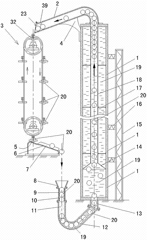
[0028] Such as figure 1 Shown: 1 is the water storage cylinder, which is fixed vertically, and the bottom and the foundation are fixedly installed. For safety and stability, a steel structure fixing frame body 15 can be arranged on the side, and a water storage cylinder body 1 and the fixing frame body 15 can be installed between the water storage cylinder body 1 and the fixing frame body 15. There are connecting beams 16. The upper end of the water storage cylinder 1 is connected with a curved float discharge pipe 2 whose port is inclined downward.

[0029] Such as Figure 5 As shown: the port of the float discharge pipe 2 is provided with a baffle 23 for controlling the discharge of the float 20 at intervals. The pin shaft 22 is rotatably connected with the support plate 21 , a first magnetic block 24 is arranged on the bottom of the baffle plate 23 , and a second magnetic block 25 matching the first magnetic block 24 is arranged at the bottom of the port of the float disc...


PUM


Abstract

The continuous gravitational potential energy power generation device includes a water storage cylinder, the upper end of the water storage cylinder is connected with a floating ball discharge pipe, and the lower end of the water storage cylinder is connected with a floating ball inlet pipe; the inner side of the floating ball inlet pipe is equipped with a sealing sleeve with a small upper mouth and a large lower mouth; The upper port of the float inlet pipe is connected with the float cone inlet; there is a gravity transmission mechanism at the port of the float ball discharge pipe. The upper bearing seat and the lower bearing seat of the gravity transmission mechanism are supported on the upper bearing seat and the lower bearing seat. The upper and lower rotating wheel pairs are equipped with transmission parts; the hanging baskets are installed at intervals on the transmission parts; the hanging baskets are matched with the floating ball; the port of the floating ball discharge pipe is located at The uppermost hanging basket in the gravity transmission mechanism; the port of the floating ball discharge pipe is provided with a baffle for controlling the discharge of the floating balls at intervals; the upper rotating wheel pair and/or the lower rotating wheel pair are connected with a generator; under the gravity transmission mechanism There is an inclined floating ball sliding groove. The upper end of the floating ball sliding groove is provided with a protrusion for the collision of the floating ball. The lower port of the floating ball sliding groove is located directly above the conical inlet of the floating ball. Control the floating balls to be discharged at intervals.

Description

technical field [0001] The invention relates to a power generation device, in particular to a continuous gravitational potential energy power generation device. Background technique [0002] At present, common power generation methods include the following: [0003] 1. Hydroelectric power generation requires the river to be cut off and dammed, so it can only be realized if the location is convenient. Many areas far away from the river in the world cannot use this method; at the same time, building hydropower plants on the river is mostly still It will cause a certain ecological impact; finally, its overall resources are limited, even if all the hydropower resources available in the world are used to generate electricity, it will eventually not be able to meet the increasing electricity demand of mankind. [0004] 2. The advantage of thermal power generation is that it has no geographical restrictions. As long as there is enough supply of fossil energy, it can continue to ex...

Claims


Application Information

Patent Timeline
Patent Type & Authority Applications(China)
IPC IPC(8): F03B17/02F03B13/00
CPCY02E10/20F03B17/02F03B13/00F05B2220/706
Inventor 王镝王彩璇丁君
Owner 王镝
Why Eureka
Try Eureka