Pilot-operated type steam hydrophobic valve

A steam trap and pilot-operated technology, applied in the direction of steam traps, mechanical equipment, etc., can solve the problems of increased steam leakage, easy wear of ball valves, and low working pressure, so as to reduce the number of times, prolong the service life, and improve the load capacity. Effect

Pending Publication Date: 2017-08-18
HUZHOU VOCATIONAL TECH COLLEGE
View PDF0 Cites 6 Cited by
  • Summary
  • Abstract
  • Description
  • Claims
  • Application Information

AI Technical Summary

Problems solved by technology

[0005] The main problem is that the ball valve is easy to wear under the action of steam pulsation, and the leakage of steam i

Method used


Image

  • Pilot-operated type steam hydrophobic valve
  • Pilot-operated type steam hydrophobic valve
  • Pilot-operated type steam hydrophobic valve

Examples


Embodiment 1

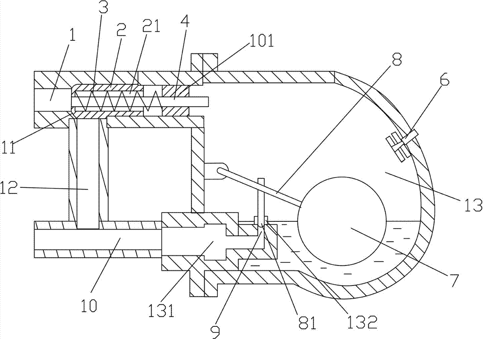
[0040]A pilot-operated steam trap, comprising a valve body with a main valve cavity 13, a floating ball 7 is arranged in the main valve cavity, and inlet valves communicated with the main valve cavity are respectively provided on the upper and lower parts of the valve body. The air port 1 and the liquid discharge port 10, the liquid discharge channel 12 is also communicated between the air inlet port and the liquid discharge port, and the upper and middle wall of the main valve chamber is also provided with an openable air outlet hole, so The air inlet is provided with a main valve core 2 for opening and closing the liquid discharge channel and having a throttling tube 4 coaxially arranged with the air inlet for ventilation, and the throttling tube runs through the main The spool communicates with the inside and outside of the main spool.

[0041] The inner end connected to the main valve chamber on the air inlet is provided with a limit ring 101, the throttle tube passes thro...

Embodiment 2

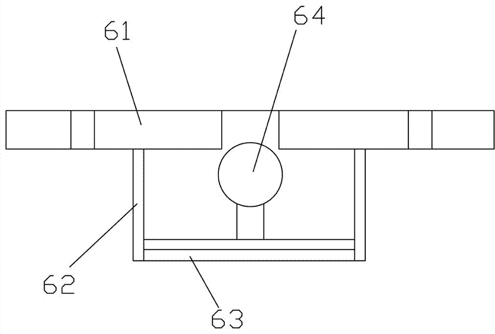
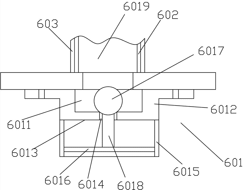
[0046] The difference from the above embodiment is that the air outlet is provided with an emptying valve 6, and the emptying valve is a bimetal valve. The bimetal valve includes a flange 61 fixed on the air outlet with a through hole corresponding to the air outlet, a support frame 62 fixed on the flange and located in the main valve cavity, fixed on the support The two stacked metal sheets 63 on the frame are fixed on the metal sheet and set corresponding to the through holes on the flange, and can open or block the through holes according to the thermal expansion and contraction of the metal sheets. 64.

[0047] The design of the bimetal sheet is to drive the valve plug to work through the deformation of two metal sheets with different expansion coefficients when the temperature changes.

[0048] The air outlet is arranged on the side of the main valve chamber wall opposite to the air inlet, and the air inlet and liquid outlet are located on the same side of the main valve...

Embodiment 3

[0050] The difference from the above embodiments is that the top of the main valve chamber is provided with a manual emptying valve 5 .


PUM


Abstract

The invention belongs to the field of steam traps, in particular to a pilot-operated steam trap. It includes a valve body with a main valve cavity, a floating ball is arranged in the main valve cavity, an air inlet and a liquid discharge port communicated with the main valve cavity are respectively arranged on the upper part and the lower part of the valve body, and the inlet and outlet There is also a liquid discharge channel connected between the gas port and the liquid discharge port, and an openable air outlet hole is provided on the middle and upper wall of the main valve chamber, and a vent hole for opening and closing the liquid discharge port is provided on the air inlet port. The main valve core is channeled and has a throttling tube for venting coaxially arranged with the air inlet, and the throttle tube passes through the main valve core to communicate with the inside and outside of the main valve core. In this application, the pilot water-type design is carried out on the liquid discharge channel between the air inlet and the liquid outlet, which greatly improves the load capacity of the valve body, and the valve body may be suitable for application in high-pressure places. The throttling tube of the present application can effectively suppress steam pulsation, reduce the vibration of the floating ball, and prolong its working life.

Description

technical field [0001] The invention belongs to the field of steam traps, in particular to a pilot-operated steam trap. Background technique [0002] Steam traps are widely used in petroleum, chemical, nuclear power, wood-based panel industries, and are widely used. The basic function of the steam trap is to discharge the condensed water, air and carbon dioxide gas in the steam system as soon as possible; at the same time, it can automatically prevent the leakage of steam to the greatest extent. The quality of steam traps is very important to environmental protection and energy saving, especially the impact on energy saving is particularly prominent, and its design has always been a hot research topic in this industry. Some of the steam traps we currently use are still imported, but the localization rate is gradually increasing. [0003] The steam trap plays the role of blocking steam and draining water in the steam heating system. Choosing a suitable steam trap can make t...

Claims


Application Information

Patent Timeline
IPC IPC(8): F16T1/38F16T1/20
CPCF16T1/20F16T1/38
Inventor 何彦虎陆勤丰
Owner HUZHOU VOCATIONAL TECH COLLEGE
Why Eureka
Try Eureka