

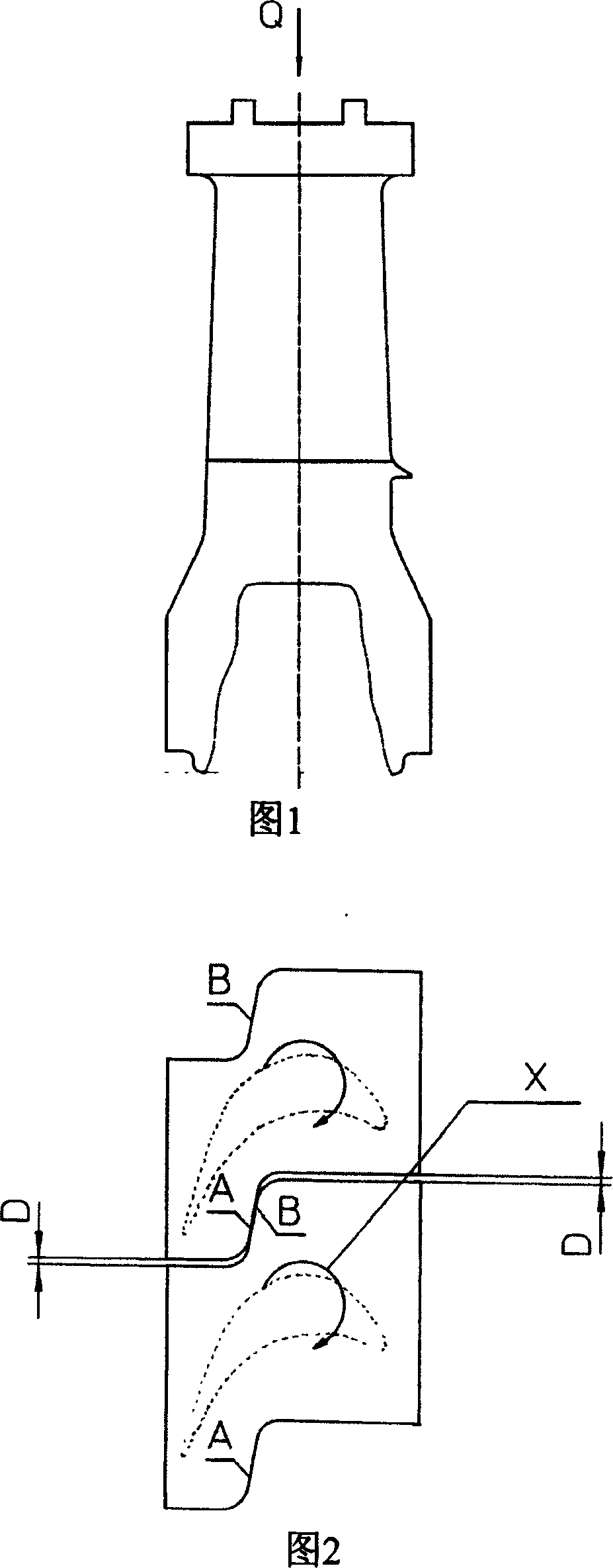
Steam turbine moving vane shroud structure
A moving blade and maneuvering technology, applied in the direction of machine/engine, blade supporting element, mechanical equipment, etc., can solve the problems of poor fit of the radial mating surface of the shroud, inconsistent torsion, and difficulty in blade processing and assembly.
- Summary
- Abstract
- Description
- Claims
- Application Information
AI Technical Summary
Problems solved by technology
Method used
Image

Examples
Embodiment Construction
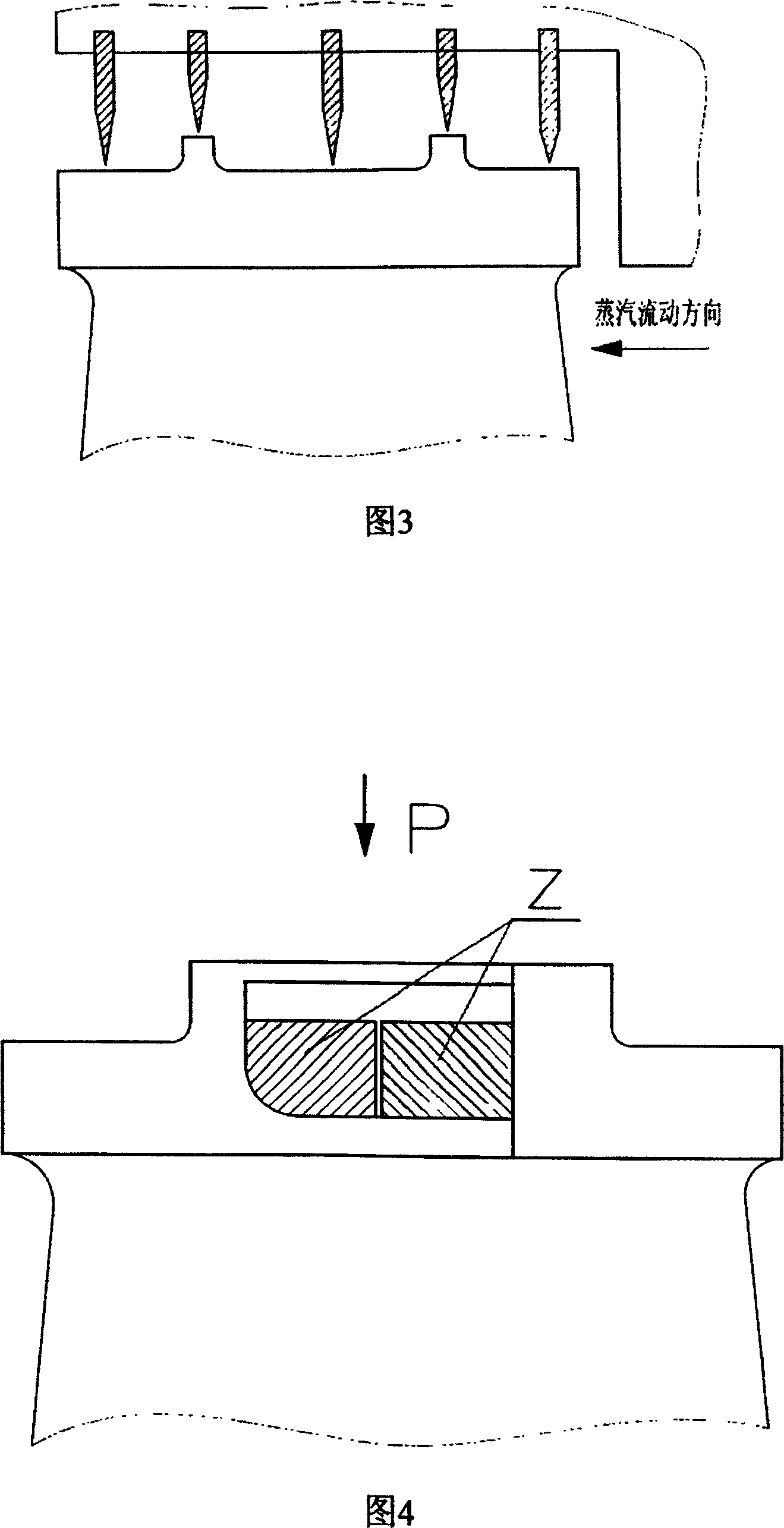
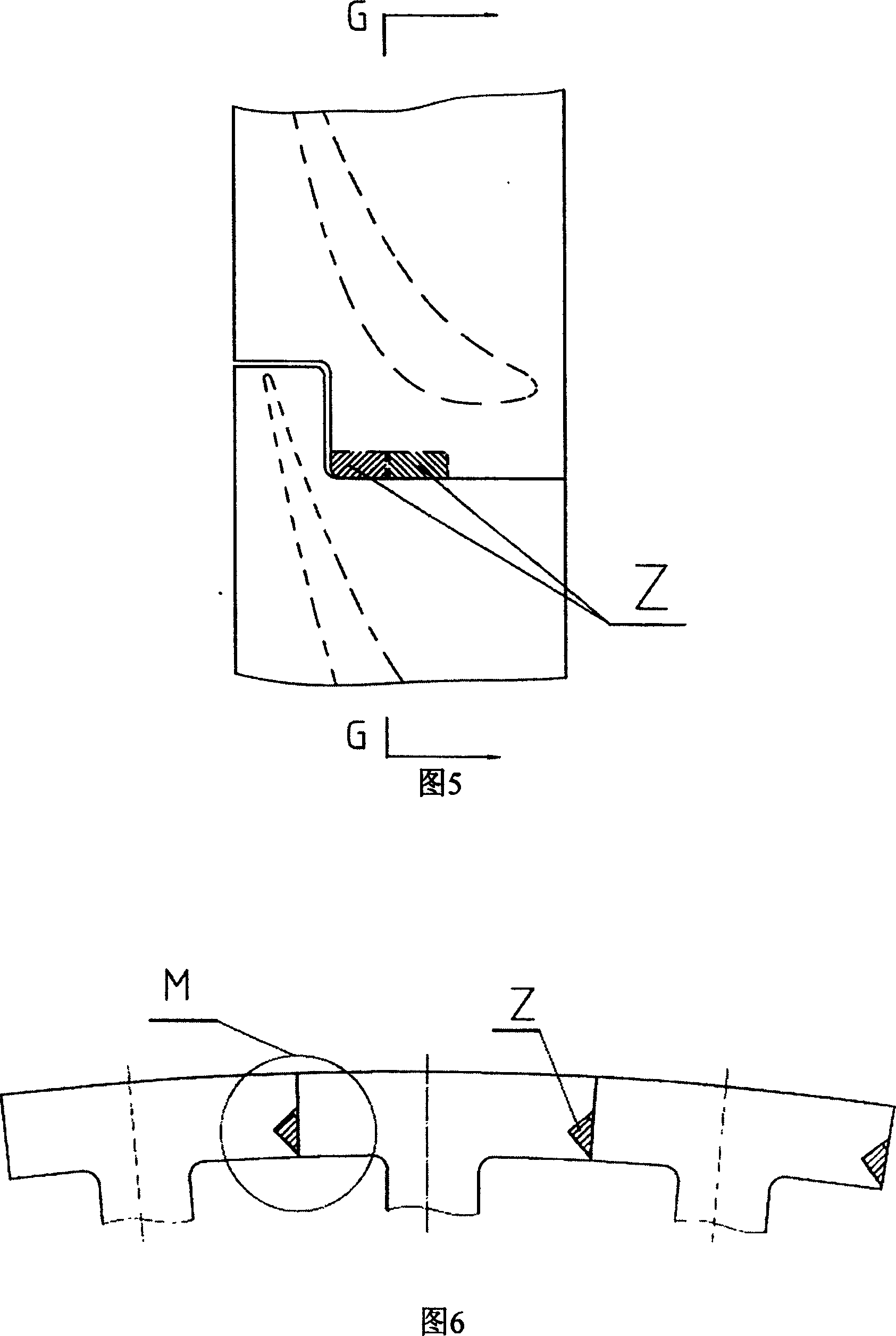
[0021] See Fig. 4 to Fig. 7: The notable feature of the shroud of the motor blade of the steam turbine is that a damper Z is added on the radial mating surface of the shroud, and a cross section is milled into a "V" shape on the radial mating surface of the shroud. The axial groove of the damper Z is located in the groove, and its shape is adapted to the groove. The principle is shown in Figure 7. When the unit is running, on the one hand, the blades are twisted and deformed; on the other hand, the damper Z is under its centrifugal force F Under the action of , it will move in the S direction. When the displacement reaches the point where its D surface contacts the E surface of the adjacent blade, the displacement stops and damping occurs. The centrifugal force F of the damper Z is decomposed into component forces F1 and F2, which act respectively For two adjacent blades, thereby increasing the structural rigidity of the blade and reducing the dynamic stress. The mechanical da...
PUM
 Abstract
Description
Claims
Application Information