Incident drift angle automatic identifying and error compensating method in ultrasonic thickness measurement

An automatic identification and error compensation technology, applied in the direction of using ultrasonic/sonic/infrasonic waves, measuring devices, instruments, etc., can solve the incident deviation angle thickness measurement error, the centerline of the ultrasonic sensor sound beam and the normal vector of the measuring point cannot maintain real-time coincidence and other problems, to achieve the effect of high reliability, fast operation speed and high inverse calculation accuracy

Active Publication Date: 2017-08-18
DALIAN UNIV OF TECH
View PDF2 Cites 6 Cited by
  • Summary
  • Abstract
  • Description
  • Claims
  • Application Information

AI Technical Summary

Problems solved by technology

[0006] The technical problem mainly solved by the present invention is to overcome the deficiencies of the existing methods. In the ultrasonic automatic thickness measurement, the center line of the ultrasonic sensor sound beam and the normal vector of the measure

Method used


Image

  • Incident drift angle automatic identifying and error compensating method in ultrasonic thickness measurement
  • Incident drift angle automatic identifying and error compensating method in ultrasonic thickness measurement
  • Incident drift angle automatic identifying and error compensating method in ultrasonic thickness measurement

Examples


Embodiment Construction

[0046] The embodiment of the present invention is described in detail in conjunction with the accompanying drawings and technical solutions, and the automatic identification and error compensation method of the incident deflection angle in the ultrasonic on-machine thickness measurement is described.

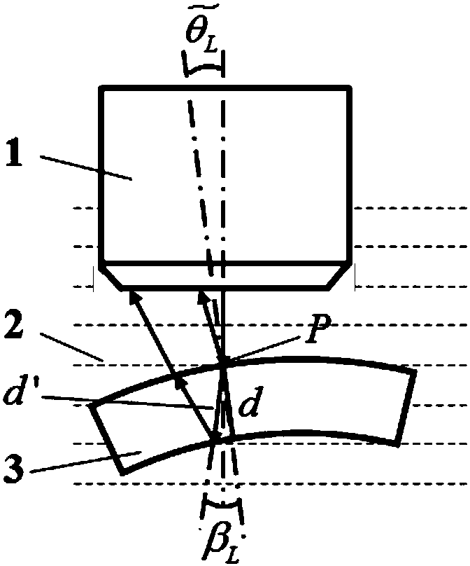
[0047] Measurement parameters: Calibration piece 7, material 45 steel, standard cuboid measuring block, design size is 30mm×30mm×5mm; tested piece 3, material 45 steel, curved piece, design thickness 8mm, radius 48mm; water immersion type Ultrasonic flat probe, pulse width 10MHz, chip diameter 6.35mm, acquisition frequency 1.25GHz.

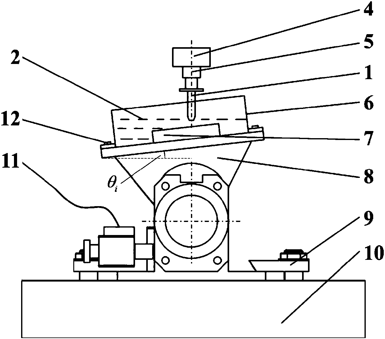
[0048] The first step is preparation for calibration of ultrasonic incidence deflection angle. The schematic diagram of the incident declination angle calibration is shown in figure 1 shown. The ultrasonic sensor 1 is installed on the main shaft 4 through the fixture 5, the rotating platform 8 is fixed on the machine tool workbench 10 through the ...


PUM


Abstract

The invention provides an incident drift angle automatic identifying and error compensating method in ultrasonic thickness measurement, wherein the method belongs to the field of ultrasonic detecting technology. Particularly the invention relates to an incident drift angle automatic identifying and error compensating method in ultrasonic thickness measurement. The method comprises the steps of firstly, performing ultrasonic incident drift angle calibration, extracting first echo energy of an ultrasonic signal at different calibration incident drift angles, and establishing an association relation between the calibration incident drift angle and the first echo energy; then, performing sampling for acquiring an actual ultrasonic thickness measurement signal of a measured member, and automatically identifying the incident drift angle by means of the association relation between the calibration incident drift angle and the first echo energy; and finally, calculating a current measuring point echo time difference, finishing incident drift angle association thickness error compensation by means of the established thickness error compensation model, and obtaining an accurate thickness measuring result. The incident drift angle automatic identifying and error compensating method realizes incident drift angle automatic identification in ultrasonic thickness measurement and association thickness error compensation thereof. Furthermore the incident drift angle automatic identifying and error compensating method has advantages of simple algorithm, high reliability and high real-time performance.

Description

technical field [0001] The invention belongs to the technical field of ultrasonic detection, and in particular relates to an automatic identification and error compensation method for incident deflection angles in ultrasonic machine thickness measurement. Background technique [0002] Because of its interface reflection and material transmission characteristics, the ultrasonic method is often the preferred method for detecting the thickness of parts in the production site. The ultrasonic sensor is integrated into the processing equipment to realize automatic thickness measurement on the machine, which can effectively solve the problem of efficient thickness measurement of large thin-walled parts. [0003] At present, ultrasonic thickness measurement mainly adopts the principle of pulse reflection, which requires that the centerline of the acoustic beam of the sensor coincides with the normal vector of the measured point, otherwise there will be an incident deflection angle. ...

Claims


Application Information

Patent Timeline
IPC IPC(8): G01B17/02
CPCG01B17/02
Inventor 王永青廉盟刘海波应杨威周连杰郭东明
Owner DALIAN UNIV OF TECH
Why Eureka
Try Eureka