Magnetic resonance imaging method and magnetic resonance imaging equipment

A magnetic resonance imaging and magnetic resonance signal technology, applied in magnetic resonance measurement, using nuclear magnetic resonance imaging system for measurement, measuring magnetic variables, etc., can solve problems such as inconsistent suppression of lamellar fat, affecting diagnosis, fat signal jumps, etc. , to achieve the effect of alleviating the irregular timing

Active Publication Date: 2019-12-03
SHANGHAI UNITED IMAGING HEALTHCARE
View PDF5 Cites 0 Cited by
  • Summary
  • Abstract
  • Description
  • Claims
  • Application Information

AI Technical Summary

Problems solved by technology

[0003] In magnetic resonance imaging, because the nuclear spin signal of some special tissues (such as adipose tissue) is too strong, it may cover up the lesion. Taking adipose tissue as an example, in order to suppress the nuclear spin signal of adipose tissue, usually magnetic The resonance imaging sequence and the magnetic resonance frequency selective fat suppression sequence are used together to suppress the fat signal, and the irregularity of the frequency sequence of the magnetic resonance frequency selective fat suppression sequence leads to a jump in the fat suppression effect between layers, that is, different layers of fat suppression The degree is inconsistent. Doctors often feel that the jump between layers is particularly eye-catching when reading the film. In severe cases, it will affect the diagnosis.
[0004] The reason for the layer-to-layer jump of fat signal intensity is that for the clinical application of respiratory bandage or navigation trigger, the irregular sequence timing makes the fat longitudinal magnetization vector have not yet reached a stable level when fat suppression is performed on the first few slices scanned. state, and the RF pulse flip angle of the fat-pressing module on each layer is the same, so the fat longitudinal magnetization vector after the fat-pressing module is different for each layer, which eventually leads to inter-layer jumps in the fat signal intensity on the image

Method used


Image

  • Magnetic resonance imaging method and magnetic resonance imaging equipment
  • Magnetic resonance imaging method and magnetic resonance imaging equipment
  • Magnetic resonance imaging method and magnetic resonance imaging equipment

Examples


Embodiment 1

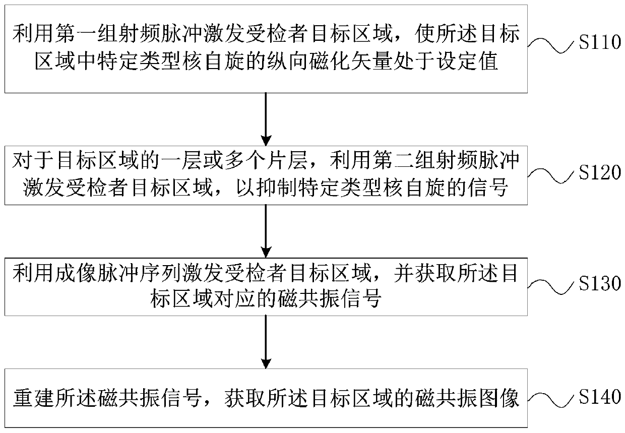
[0028] figure 1 It is a schematic flow chart of a magnetic resonance imaging method provided by Embodiment 1 of the present invention. This embodiment is applicable to the case where radio frequency pulses are used to excite the target area of ​​the subject and reconstruct magnetic resonance signals for magnetic resonance imaging. This method can be performed by The apparatus can be implemented by magnetic resonance imaging equipment, and the apparatus can be realized by means of hardware and / or software. refer to figure 1 , the magnetic resonance imaging method provided in this embodiment specifically includes:

[0029] S110. Using the first group of radio frequency pulses to excite the subject's target area, so that the longitudinal magnetization vector of a specific type of nuclear spin in the target area is at a set value.

[0030] Among them, due to the different molecular environments of hydrogen protons in human body such as adipose tissue and hydrogen protons in othe...

Embodiment 2

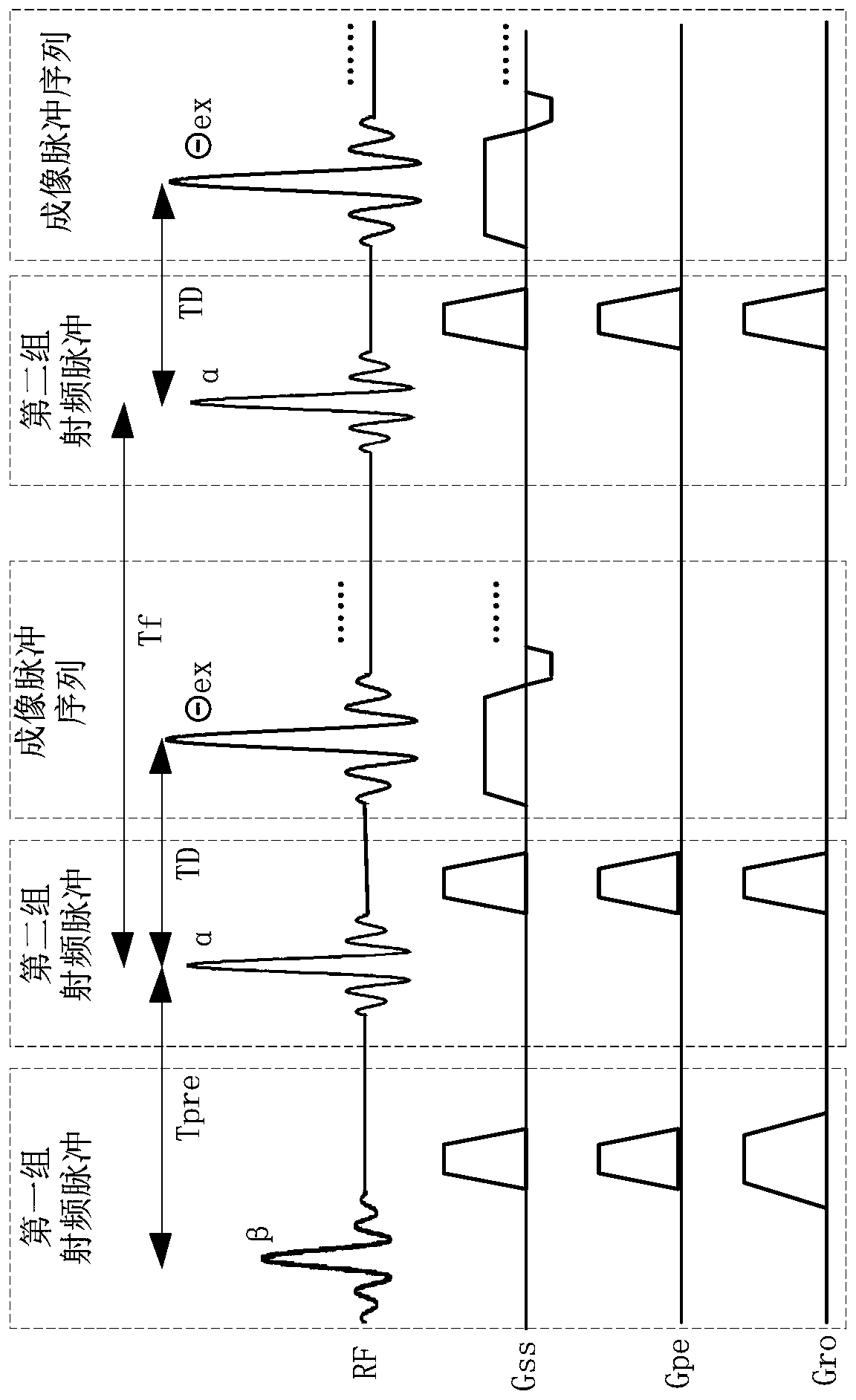
[0054] In this embodiment, on the basis of the above-mentioned embodiments, it is preferable to further optimize the first group of radio frequency pulses and the second group of radio frequency pulses as follows: the first group of radio frequency pulses includes at least one 90° radio frequency pulse, and the first group of radio frequency pulses There is a first set time interval between the last 90° radio frequency pulse and the second group of radio frequency pulses, and the second group of radio frequency pulses includes at least one 180° radio frequency pulse.

[0055] The specific process of magnetic resonance imaging includes: applying a first group of radio frequency pulses (such as one or a plurality of 90° radio frequency pulses) to the first layer of the subject's target area, so that the fat longitudinal magnetization vector (of course, the water protons can also be selected) (longitudinal magnetization vector) uniformly flipped to 0, and after the interval of the...

Embodiment 3

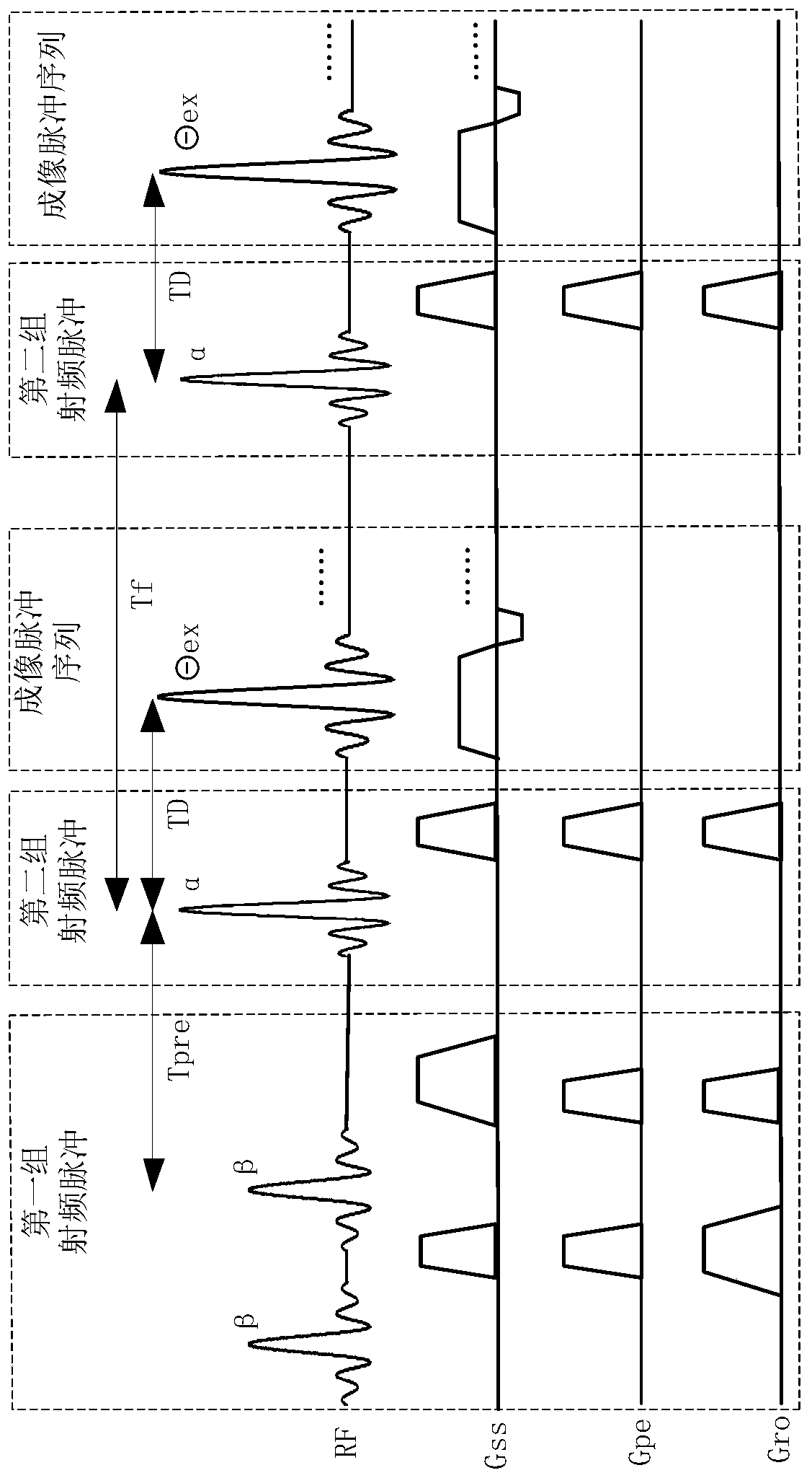
[0061] In this embodiment, on the basis of Embodiment 1, it is preferable to further optimize the first group of radio frequency pulses and the second group of radio frequency pulses as follows: the first group of radio frequency pulses includes at least one 90° radio frequency pulse, and the first group of radio frequency pulses There is a second set time interval between the last 90° radio frequency pulse and the second group of radio frequency pulses, and the second group of radio frequency pulses includes at least one 180° radio frequency pulse.

[0062] The specific process of magnetic resonance imaging includes: applying a first group of radio frequency pulses (such as one or a plurality of 90° radio frequency pulses) to the first layer of the subject's target area, so that the fat longitudinal magnetization vector (of course, the water protons can also be selected) Longitudinal magnetization vector) uniformly flipped to 0, after the interval of the second set time, the f...


PUM


Abstract

An embodiment of the invention discloses a magnetic resonance imaging method and a magnetic resonance imaging device. The method comprises the following steps: exciting a target area of a subject by utilizing a first group of radio-frequency pulses to enable a longitudinal magnetic vector of a specific type of nuclear spin in the target area to be in a set value; for at least one or more slice layers in the target area, exciting the target area of the subject by utilizing a second group of radio-frequency pulses to suppress signals of the specific type of nuclear spin; exciting the target area of the subject by utilizing an imaging pulse sequence and obtaining magnetic resonance signals corresponding to the target area; and reconstructing the magnetic resonance signals, and obtaining a magnetic resonance image of the target area. The magnetic resonance imaging method and the magnetic resonance imaging device can reduce the phenomenon of interlayer jump of signal intensity of special tissues.

Description

technical field [0001] Embodiments of the present invention relate to the technical field of magnetic resonance imaging, and in particular, to a magnetic resonance imaging method and a magnetic resonance imaging device. Background technique [0002] The principle of Magnetic Resonance Imaging (MRI) is: by applying a gradient magnetic field and RF waves to a target object in a static magnetic field, and giving a magnetic resonance (Magnetic Resonance , MR) signals to reconstruct the structural image corresponding to the target inspection object. The application of this technology in clinical diagnosis and scientific research has become a reality, which has greatly promoted the rapid development of medicine, neurophysiology and cognitive neuroscience. [0003] In magnetic resonance imaging, because the nuclear spin signal of some special tissues (such as adipose tissue) is too strong, it may cover up the lesion. Taking adipose tissue as an example, in order to suppress the nu...

Claims


Application Information

Patent Timeline
Patent Type & Authority Patents(China)
IPC IPC(8): G01R33/48A61B5/055
CPCA61B5/055G01R33/4831G01R33/4833G01R33/4838
Inventor 刘柳宋瑞波薛爱国
Owner SHANGHAI UNITED IMAGING HEALTHCARE
Why Eureka
Try Eureka