Exposure device

A technology of exposure device and exposure hole, which is applied in photoplate-making process exposure device, microlithography exposure equipment, optics, etc., can solve the problems of reducing exposure accuracy and the like

Active Publication Date: 2017-08-18
WUHAN CHINA STAR OPTOELECTRONICS TECH CO LTD
View PDF6 Cites 2 Cited by
  • Summary
  • Abstract
  • Description
  • Claims
  • Application Information

AI Technical Summary

Problems solved by technology

[0004] The invention provides an exposure device to solve the technical problem of reducing the exposure accuracy because of the diffracted light generated on the side of the exposure hole in the baffle, which exposes the parts that do not need to be exposed in the product

Method used


Image

  • Exposure device
  • Exposure device
  • Exposure device

Examples


Embodiment Construction

[0021] The following descriptions of the various embodiments refer to the accompanying drawings to illustrate specific embodiments in which the present invention can be practiced. The directional terms mentioned in the present invention, such as "up", "down", "front", "back", "left", "right", "inside", "outside", "side", etc., are for reference only The orientation of the attached schema. Therefore, the directional terms used are used to illustrate and understand the present invention, but not to limit the present invention.

[0022] In the figures, structurally similar units are denoted by the same reference numerals.

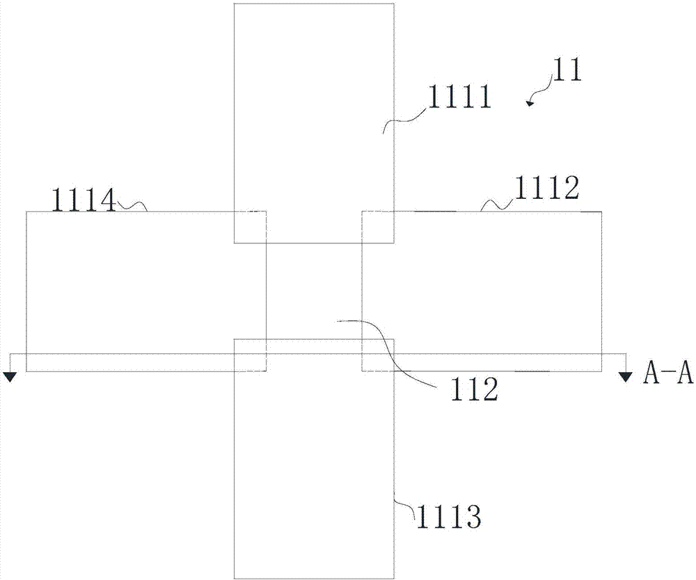
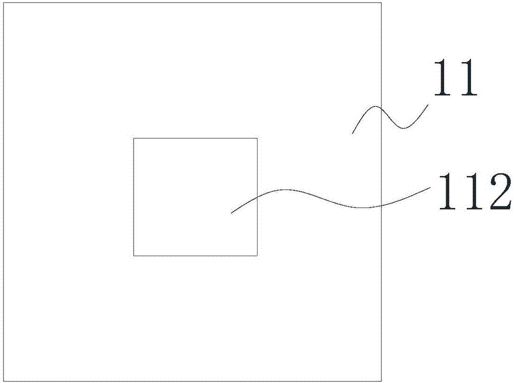
[0023] Please refer to Figure 1 to Figure 5 shown. An embodiment of the present invention provides an exposure device, which includes a baffle assembly 11 and a lens assembly 12 .

[0024] See figure 1 as shown, figure 1 It is a schematic top view structure diagram of the baffle assembly in the exposure device provided by the embodiment of the present i...


PUM


Abstract

The invention provides an exposure device. The exposure device comprises a baffle assembly and a lens assembly, wherein an exposure hole is formed in the baffle plate assembly, and the lens assembly is arranged between the baffle plate assembly and a substrate to be exposed and is used for converging a diffraction light ray generated by a side edge of the exposure hole onto a region to be exposed of the substrate to be exposed. By the exposure, relatively high exposure accuracy can be achieved, and the exposure quality of the substrate to be exposed is improved.

Description

technical field [0001] The invention relates to the technical field of optical processing, in particular to an exposure device. Background technique [0002] When using an exposure machine for exposure, it is generally necessary to use a baffle, and an exposure hole is set in the baffle, and the light source will expose the area of ​​the product corresponding to the exposure hole, thereby forming the desired pattern on the product. However, when the light encounters the baffle in the process of linear propagation, diffraction will occur, that is, diffraction will occur at the side of the exposure hole, and the area corresponding to the diffraction area in the product will also have a certain degree of exposure, which leads to the actual product. The difference between the manufactured shape and the required shape is large, which greatly reduces the exposure accuracy of the exposure machine and affects the quality of the product. [0003] Therefore, it is necessary to provid...

Claims


Application Information

Patent Timeline
Patent Type & Authority Applications(China)
IPC IPC(8): G03F7/20
CPCG03F7/70058G03F7/7015
Inventor 胡俊艳
Owner WUHAN CHINA STAR OPTOELECTRONICS TECH CO LTD
Why Eureka
Try Eureka