

Dynamically tuning device and tuning method for sending terminal of wireless electric energy transmission device
A wireless power transmission and tuning device technology, which is applied in the direction of circuit devices, battery circuit devices, electrical components, etc., can solve the problems of large leakage inductance of sending coils and receiving coils, line changes, and difficult changes, so as to improve transmission power and The effect of high efficiency, high active power and high tuning accuracy
- Summary
- Abstract
- Description
- Claims
- Application Information
AI Technical Summary
Problems solved by technology
Method used
Image

Examples
Embodiment 1
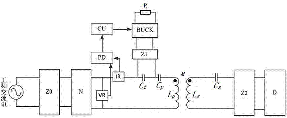
[0029] Such as figure 1 , a dynamic tuning device at the sending end of a wireless power transmission device, including a primary side and a secondary side, an AC power supply connected to the input terminal of the primary side through the primary side rectifier bridge Z0 connected to the inverter N, the inverter N and the primary side coil L P There are voltage sensor VR, current sensor IR, tuning device and static compensation capacitor C connected in sequence P , the tuning device includes a parallel rectifier bridge Z1 and a capacitor C t , the output terminal of the rectifier bridge Z1 is connected to a BUCK circuit, the output terminal of the BUCK circuit is connected to a resistor R, the output terminals of the voltage sensor VR and the current sensor IR are connected to the phase detection device PD, and the output terminal of the phase detection device PD is connected to the control unit CU The input terminal is connected, and the control unit CU outputs the driving ...
Embodiment 2
[0032] Such as figure 1 , a dynamic tuning device at the sending end of a wireless power transmission device, including a primary side and a secondary side, an AC power supply connected to the input terminal of the primary side through the primary side rectifier bridge Z0 connected to the inverter N, the inverter N and the primary side coil L P There are voltage sensor VR, current sensor IR, tuning device and static compensation capacitor C connected in sequence P , the tuning device includes a parallel rectifier bridge Z1 and a capacitor C t , the output terminal of the rectifier bridge Z1 is connected to a BUCK circuit, the output terminal of the BUCK circuit is connected to a resistor R, the output terminals of the voltage sensor VR and the current sensor IR are connected to the phase detection device PD, and the output terminal of the phase detection device PD is connected to the control unit CU The input terminal is connected, and the control unit CU outputs the driving ...
Embodiment 3
[0038] Such as figure 1 , a tuning method for a dynamic tuning device at a sending end of a wireless power transmission device, characterized in that it includes the following steps:
[0039] Step 1, the phase measurement device PD detects the phase of the output voltage and current of the inverter to obtain the phase difference θ 0 , to determine the resonance state of the primary side;
[0040] Step 2, if it is judged in step 1 that the primary side is not resonant, the control unit CU outputs the drive signal to adjust
[0041] BUCK circuit, so that the input equivalent resistance of the BUCK circuit reaches the reference resistance R 0 , and R 0 ≥R, R is the resistance resistance connected to the output terminal of the BUCK circuit;
[0042] Step 3, adjust the input equivalent resistance of the BUCK circuit to the minimum reference resistance R by adjusting the output driving signal of the control unit CU 1 and a large reference resistance R 2 , the input equivalent ...
PUM
 Abstract
Description
Claims
Application Information