
Winding method of motor rotor

A technology of a motor rotor and a winding method, which is applied in the field of motor rotor winding, can solve the problems of poor motor electromagnetic compatibility, slow motor starting speed, and small motor stall torque, so as to improve electromagnetic compatibility and improve stall torque. , the effect of small starting current

Inactive Publication Date: 2017-08-18
重庆奥兴嘉科技有限公司
View PDF3 Cites 4 Cited by
  • Summary
  • Abstract
  • Description
  • Claims
  • Application Information

AI Technical Summary

Problems solved by technology

[0004] Aiming at the deficiencies in the prior art, the purpose of the present invention is to provide a winding method for the motor rotor; in order to solve the problems in the prior art, the stalling torque of the motor is small, which leads to slow starting speed and large starting current of the motor. And in the process of motor commutation, the current is unstable, and commutation sparks are easily generated, so that the electromagnetic compatibility of the motor is poor.

Method used


Image

  • Winding method of motor rotor
  • Winding method of motor rotor
  • Winding method of motor rotor

Examples


Embodiment 1

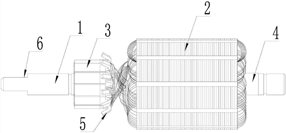
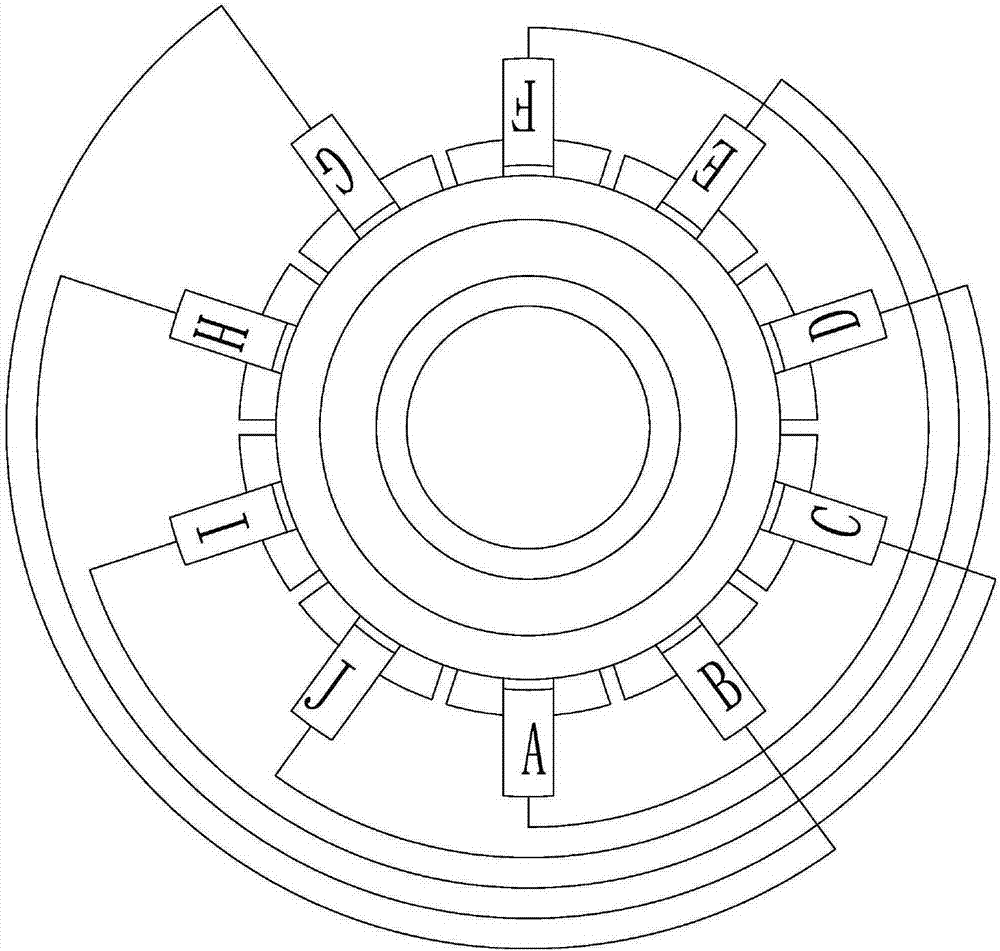
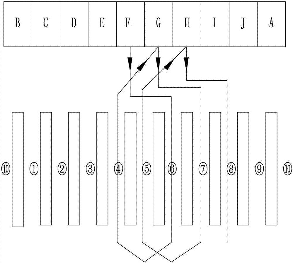
[0017] refer to Figure 1 ~ Figure 3 Shown: a winding method of a motor rotor, the motor rotor includes a rotating shaft 1, the middle of the rotating shaft 1 is provided with an insulating groove 4 in the circumferential direction, and 10 silicon steel sheets 2 arranged at intervals are evenly distributed in the circumferential direction of the insulating groove 4; the insulating groove The setting of 4 plays the role of protective insulation, avoiding the direct connection of the winding wire with the shaft 1, causing a short circuit; the silicon steel sheet 2 can reduce the heat generation and the electromagnetic interference to the surrounding environment, and through the setting of the silicon steel sheet 2, the There are 10 winding grooves formed between silicon steel sheets 2, and the winding grooves are silicon steel sheet groove ①, silicon steel sheet groove ②, silicon steel sheet groove ③, silicon steel sheet groove ④, silicon steel sheet groove ⑤, silicon steel sheet...


PUM


Abstract

The invention discloses a winding method for a motor rotor. The winding of a rotor has four steps: in a step S1, a wire segment is wound around the rotating shaft of the motor for 360 DEG, then is hung on a winding hook F on a commutator of the motor rotor, and is hang on a winding hook A after winding along the rotation shaft of the motor for 180 DEG; in a step S2, a tail wire segment is wound into a silicon steel groove (4) from a starting winding groove, and is wound around the rotation shaft of the motor for 360 DEG, then is hung on a winding hook G after winding, then rotates along the rotation shaft of the motor for 180 DEG and is hung on a winding hook B, and then is wound along the motor shaft of the motor for 180 DEG and hung into a silicon steel groove (7), and the relative position of the silicon steel groove (7) in the starting winding groove is the same as the relative position of the winding hook G in the winding hook F. Compared with the prior art, the method improves the stall torque of the motor, so that the starting speed of the motor is fast, the starting current is small. Meanwhile, the voltage of the motor is stable in the process of commutation, commutation sparks are avoided, and the motor electromagnetic compatibility is improved.

Description

technical field [0001] The invention relates to the field of motors, in particular to a winding method for a motor rotor. Background technique [0002] At present, in all kinds of motors seen, the stator windings are composed of silicon steel sheet groups and enameled wires (or copper bars), and the silicon steel sheet groups are composed of multiple silicon steel sheets arranged at intervals. The silicon steel sheet slots are formed at intervals, and the enameled wire is wound in the slot of the silicon steel sheet according to the specified rules, and the effective parts of the enameled wire are all wound in the slot of the silicon steel sheet toward the center of the circle. This winding method keeps the wire parallel to the magnetic field, enabling the wire to do a "cutting magnetic field line" motion. At the same time, silicon steel sheet, a high magnetic permeability material, plays a vital role in improving the operating efficiency of the motor. [0003] The existin...

Claims


Application Information

Patent Timeline
IPC IPC(8): H02K15/09
CPCH02K15/09
Inventor 温健
Owner 重庆奥兴嘉科技有限公司
Learn More