Method for shortening same PN-RRU time delays

A time delay and optical cable technology, applied in multiplex communication, time division multiplexing system, optical fiber transmission, etc., can solve problems such as large delay, unsolvable delay problem, and inability to compensate, so as to reduce delay , Maximization of resource efficiency, and the effect of solving delay problems

Inactive Publication Date: 2017-08-18
CHINA TELECOM CORP LTD
View PDF5 Cites 0 Cited by
  • Summary
  • Abstract
  • Description
  • Claims
  • Application Information

AI Technical Summary

Problems solved by technology

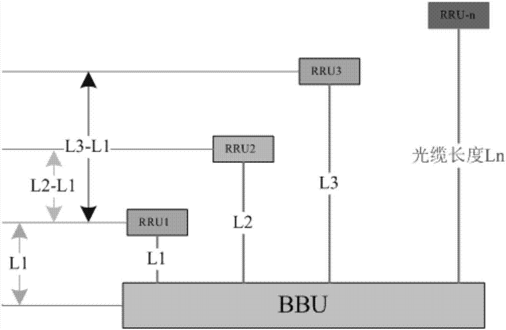
[0004] Although the same PN technology of equipment manufacturers solves the problem of interference between signals, it will bring a new problem - the problem of delay
If the optical cable delay of RRU2 and RRU3 is very long, the delay of RRU2 (the delay generated by the L2-L1 segment of the optical cable) and the delay of RRU3 (the delay generated by the L3-L1 segment of the optical cable) will be very large, the same as the PN Technology cannot compensate for these interference issues
If the delay is too long, it will affect the signal search speed of the mobile phone, especially in the high-speed scenario of high-speed rail, the signal search is not timely and it is easy to cause disconnection
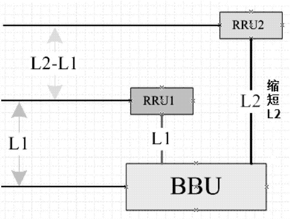
[0005] The traditional method to solve the delay is mainly to shorten the length of the optical cable with a long RRU, as shown in Figure 2 (a), the main method used is to use a direct routing connection without jumping, which can solve the problem Part of the fiber optic cable delay, but the actual situation is that direct connection routing cannot be used in many scenarios, because the deployment of optical cables requires poles or pipes, and many scenarios do not have existing poles and pipes. If new poles and pipes are used, this This kind of cost consumption is very high, and it is unaffordable under normal circumstances
[0006] Therefore, only by finding a low-cost method that can quickly solve the same PN-RRU delay problem, can this technology be better applied in the live network, otherwise, in many scenarios, it will not be possible due to the limited delay. Use the same PN technology
[0007] The Chinese patent document with the patent number CN200710087524.9 discloses a method and device for detecting same-PN interference in a CDMA system. This patent is mainly a detection device for same-PN interference in a code division multiple access system, which can accurately distinguish PN The interference problem caused by too short distance, this patented invention is mainly to find the same PN interference, but not to solve the interference
The Chinese patent document with the patent number CN201410683351.7 discloses a downlink optical fiber delay compensation method and device for LTE cell merging. This patent mainly stores the data mapped by the downlink resource in the random access memory RAM by the baseband processing unit BBU ;In a sampling period, each remote radio unit RRU connected to the BBU fiber reads its data from the RAM according to the pre-configured fiber delay, and sends it through the air interface after the RRU processing process. This patent is mainly on the device side To deal with the delay problem caused by the merger of LTE cells, this patent mainly performs the shortest delay compensation, but the shortest delay compensation cannot solve the delay problem that occurs after multiple RRU cells are merged

Method used


Image

  • Method for shortening same PN-RRU time delays
  • Method for shortening same PN-RRU time delays
  • Method for shortening same PN-RRU time delays

Examples


Embodiment 1

[0041] In this embodiment, Huawei RRU equipment is used, so the RRU with the shortest optical cable length can be obtained by querying the dsp cbtsfblen command S and the longest RRU L .

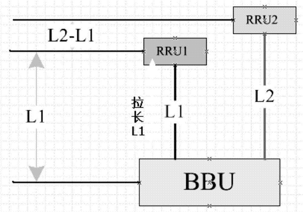
[0042] like image 3 As shown, taking the high-speed rail station Dongqing Liujia as an example, the TRM0 of Dongqing Liujia and the RRU6 and RRU7 of Zhenglu Fanjiazhuang have the same PN. The length of the optical cable in Zhenglu Fanjiazhuang is relatively long, about 5KM. The device can only compensate the time delay from TRM0 to UBRI board, but the time delay of the 5KM fiber optic cable in Zhenglu Fanjiazhuang cannot be compensated, which makes the large base station search window settings around Dongqing Liu’s home very large, which affects the search speed of mobile phones.

[0043] By adopting the method of the present invention, Dongqing Liujia TRMO is detoured to the Zhoutangqiao base station with a section of optical cable, and then connected to the Dongqing Liujia UBRI board. T...


PUM


Abstract

The invention discloses a method for shortening same PN-RRU time delays. The method comprises the following steps: an RRUS with the shortest optical cable length and an RRUL with the longest optical cable length are found out; the optical cable length L of the RRUL with the longest optical cable length is calculated; according to routing information materials, an optical cable transfer box, of which the optical cable length is the closest to L/2, is selected as a roundabout point, and the RRUS is preferentially connected to the roundabout point through an optical cable and then connected with a BBU from the roundabout point through an optical cable, so that a new optical cable path is formed, and the optical cable length of the RRUS is close to the optical cable length of the RRUL; and the steps are repeated so that the optical cable lengths of all RRUs are finally close to the optical cable length of the RRUL. The method for shortening the same PN-RRU time delays provided by the invention has the advantages that a time delay difference can be shortened through elongation of short optical cables in a scenario where long optical cables cannot be shortened, so that better same PN-RRU technical effects can be achieved, and the time delay problem caused by combination of multiple RRU cells can be completely solved.

Description

technical field [0001] The invention belongs to the technical field, and in particular relates to a method for shortening the same PN-RRU time delay. Background technique [0002] With the development of wireless communication technology, the products of communication equipment manufacturers have been gradually miniaturized, remote RRU has become very popular in many places, the density of base stations has become very dense, and the interference between signals is very serious, especially In CDMA network, the interference between signals will significantly reduce the network quality, seriously affect the call drop, and make the user's perception of use poor. Therefore, many areas use the RRU and PN technology provided by the equipment manufacturer when the capacity is allowed. The method of merging multiple cells into one cell reduces the interference between signals inside the device. This technology is widely used in the existing network, the interference problem of high...

Claims


Application Information

Patent Timeline
Patent Type & Authority Applications(China)
IPC IPC(8): H04B10/2575H04J3/06
CPCH04B10/2575H04J3/0682
Inventor 李军祥朱青
Owner CHINA TELECOM CORP LTD
Why Eureka
Try Eureka