Check patentability & draft patents in minutes with Patsnap Eureka AI!

Electric die-casting machine

A die-casting machine and electric technology, applied in the direction of mechanical equipment, shock absorbers, springs/shock absorbers, etc., can solve the problems of shortened life of one-way clutches and screw shafts, increased vibration and noise, and smooth transfer, etc. problem, achieve the effect of preventing damage, suppressing vibration and noise

Active Publication Date: 2017-08-18
TOYO MACH & METAL CO LTD
View PDF7 Cites 0 Cited by
  • Summary
  • Abstract
  • Description
  • Claims
  • Application Information

AI Technical Summary

Problems solved by technology

Therefore, the shock absorbing device described in Patent Document 1 has problems such as increased vibration and noise, poor transition from the injection molding process to the boosting process, and shortened life of the one-way clutch and screw shaft.

Method used


Image

  • Electric die-casting machine
  • Electric die-casting machine
  • Electric die-casting machine

Examples


Embodiment Construction

[0033] Embodiments of the electric die-casting machine of the present invention will be described below using the drawings.

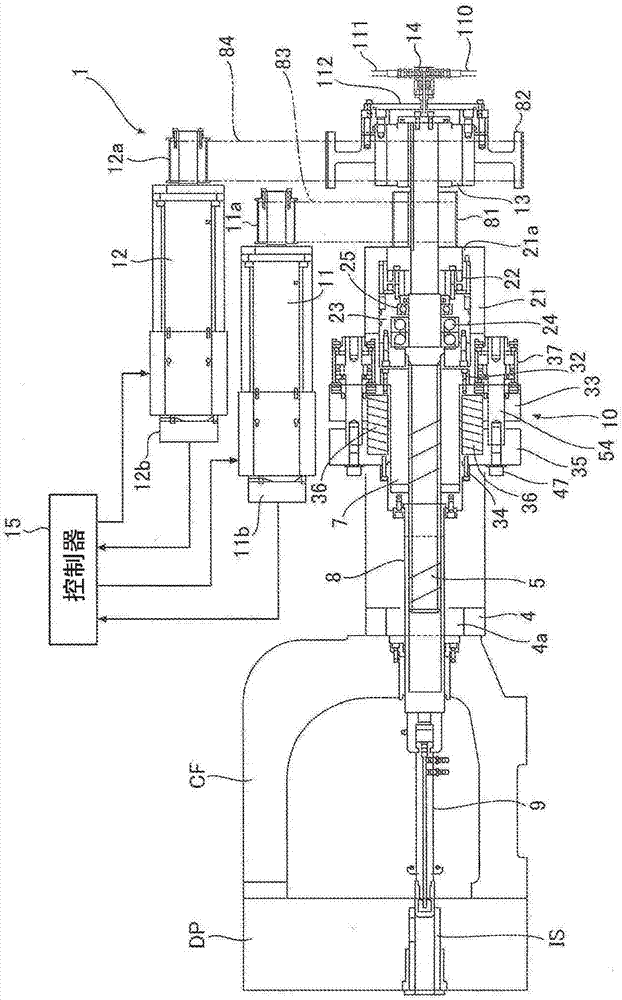
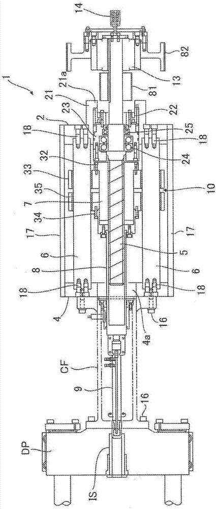
[0034] The electric die-casting machine of the embodiment has figure 1 and figure 2The electric injection molding unit 1 shown. As can be seen from the above drawings, the electric injection molding device 1 of this embodiment has: a first holding plate 2 and a second holding plate 4, the first holding plate 2 and the second holding plate 4 are arranged facing each other with a predetermined interval; Shaft 5, the screw shaft 5 is held rotatably by the first holding plate 2; guide rod 6, the two ends of the guiding rod 6 are fixed to the first holding plate 2 and the second holding plate 4; nut piece 7, the nut piece 7 is screwed with the screw shaft 5, and the nut piece 7 is driven to advance and retreat along the guide rod 6 by driving the screw shaft 5 to rotate; a cylindrical connecting piece 8, one end of which is fixed to the front end of the n...


PUM


Abstract

An electric injection device 1 of a die-casting machine is provided with: a rotatably held screw shaft 5; a nut 7 that is screwed onto the screw shaft 5; an injection plunger 9 that is driven forward and backward in conjunction with the forward and backward movement of the nut 7; an injection electric servomotor 11 and a pressure-increasing electric servomotor 12 that rotationally drive the screw shaft 5; a one-way clutch 13 that is provided between the screw shaft 5 and the pressure-increasing electric servomotor 12; and a shock buffering device 10 that absorbs surge pressure that is applied to the injection plunger 9. The shock buffering device 10 includes: an elastic member 36 that receives surge pressure that is applied to the injection plunger 9 and elastically deforms; and a hydraulic damper device 37 that absorbs the vibration of the elastic member 36.

Description

technical field [0001] The present invention relates to an electric die-casting machine, and more particularly to a shock absorber for preventing shock pressure included in an electric injection molding device for injecting and filling molten metal into a cavity of a mold. Background technique [0002] The die-casting machine drives the injection plunger equipped with the injection molding device to inject and fill a certain amount of molten metal materials such as aluminum alloy or magnesium alloy into the cavity of the mold to manufacture the die-casting products of the desired shape in each injection. molding machine. Like the injection molding machine that injects and fills plastic materials into the cavity to manufacture plastic products of the desired shape, the die-casting machine also undergoes a low-speed injection process, a high-speed injection process, and a pressurization process (called a pressure-holding process in an injection molding machine). process) to i...

Claims


Application Information

Patent Timeline
Patent Type & Authority Applications(China)
IPC IPC(8): B22D17/32F16F7/00
CPCB22D17/32F16F7/00
Inventor 中塚吉久
Owner TOYO MACH & METAL CO LTD
Features
  • R&D
  • Intellectual Property
  • Life Sciences
  • Materials
  • Tech Scout
  • Unparalleled Data Quality
  • Higher Quality Content
  • 60% Fewer Hallucinations
Learn More