High-stability self-centering drill bit

A drill tip, high stability technology, used in drilling/drilling equipment, drill repair, drilling tool accessories, etc., can solve the problems of reduced accuracy, weak centering effect, long drill bit, etc., to improve the positioning effect , good positioning effect, high verticality effect

Active Publication Date: 2017-08-22
CHENGDU FENGYI YINHU CNC TOOL CO LTD
View PDF12 Cites 18 Cited by
  • Summary
  • Abstract
  • Description
  • Claims
  • Application Information

AI Technical Summary

Problems solved by technology

If you use a long drill bit to directly drill a deep hole, often due to the long drill bit and poor rigidity, the drill tip will shake on the surface of the workpiece, and it is difficult to locate and drill into the workpiece at one point.
The precision of drilling the middle hole is low, the hole will drift and not straight, the hole wall finish is poor, and it is easy to produce ripples
[0004] For example: the invention patent with the patent number "ZL200980108586.0" discloses a cutting tool with a chisel tip, and discloses a chisel tip angle with a double margin and between 80 degrees and 100 degrees. This kind of drill tip solves the shaking problem of the drill tip to a certain extent, but in practical applications, it is often found that the centering effect is poor
The reason is that the raised chisel tip raises the chisel edge of the ordinary drill bit, which reduces the axial drilling force of drilling and makes it easier to drill into the workpiece, but the effect of preventing the radial swing of the drill bit is not strong enough, resulting in When the drilling force is greater or the feed rate is accelerated, the centering effect is still weak, and the drill tip will sway radially, causing ripples on the hole wall and reducing the accuracy of the hole.

Method used


Image

  • High-stability self-centering drill bit
  • High-stability self-centering drill bit
  • High-stability self-centering drill bit

Examples


Embodiment Construction

[0016] The present invention will be further described below in conjunction with accompanying drawing:

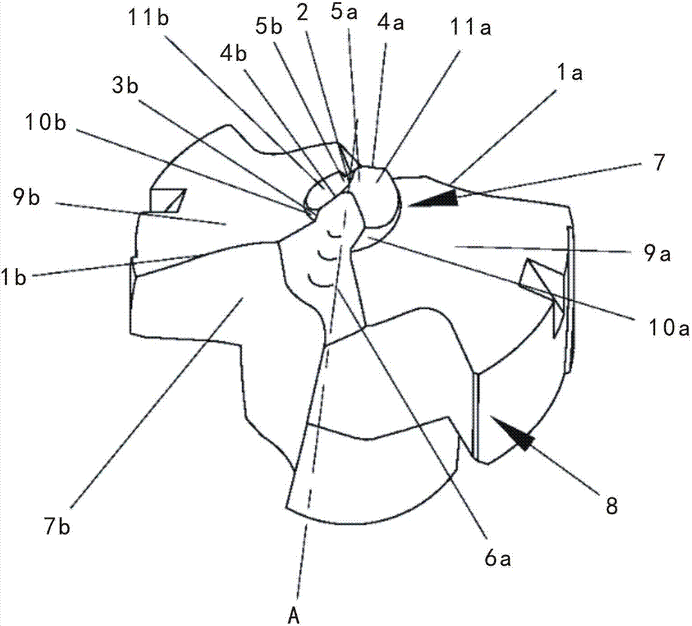
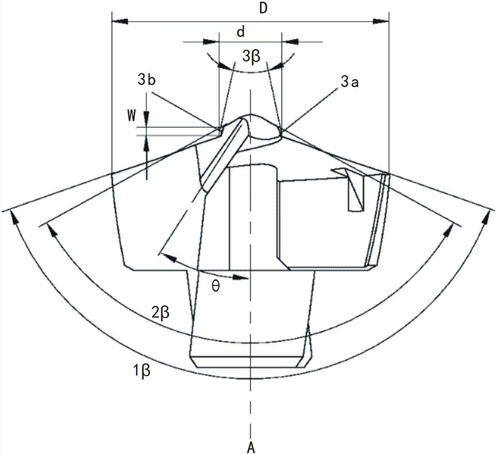
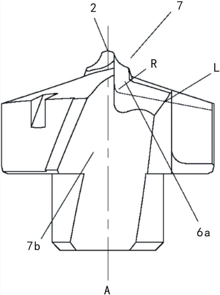
[0017] Such as Figure 1-Figure 4 As shown, the high stability self-centering drill bit 8 of the present invention is provided with two chip removal grooves 7a and 7b symmetrically on both sides, the tip of the drill tip 8 is upward, and the center of the drill tip 8 The position protrudes upwards along its center line to form a center tip 7, and the upper surfaces of the drill tip 8 located outside the two sides of the center tip 7 are outer flanks 9a and 9b respectively; the top of the center tip 7 is a line Shaped chisel edge 2, the two sides of the chisel edge 2 extend outwards and downwards in turn to be two chisel edges 5a / 5b, two inner flanks 11a / 11b and two oblique flanks 10a / 10b, the chisel edge 2 Two transition surfaces 6a and 6b are formed between the two ends of the two flutes 7a and 7b respectively, and the two transition surfaces 6a and 6b respectively inters...


PUM


Abstract

The invention discloses a high-stability self-centering drill bit. The two sides of high-stability self-centering drill bit are symmetrically provided with two chip discharge grooves, the tip of the drill bit faces upward, the center portion of the drill bit protrudes upward along the center line of the drill bit to form a central bit part, the surfaces, located outside the two sides of the central bit parts, of the upper portion of the drill bit refer to outside rear tool surfaces, the top of the central bit part is a linear chisel edge, the two sides of the chisel edge extends outward and downward to form two chisel edge surfaces, two inside rear tool surfaces and two inclined rear tool surfaces, two transition surfaces are formed between the two ends of the chisel edge and the two chip discharge grooves, the outsides of the two ends of the chisel edge are sequentially connected with two inside blades, two inclined blades and two outside blades, and the inclined blades are formed through interconnection of a straight-line blade in the middle and arc line blades at the two ends. By arranging the central bit part and arranging the chisel edge, the inside blades, the inclined blades, the chisel edge surfaces, the inside rear tool surfaces and the inclined rear tool surfaces, the positioning effect of the drill bit is significantly improved, pre-drilling is not needed, drilling can be directly conducted, and deep hole processing can be efficiently completed.

Description

technical field [0001] The invention relates to a drill point, in particular to a high-stability self-centering drill point which does not require pre-drilling for deep hole processing and has little shaking during drilling. Background technique [0002] Hole processing is one of the most common and difficult processing types in the field of modern machinery manufacturing. It is widely used in various fields, such as general machinery, auto parts manufacturing, aerospace, engineering machinery, electrical machinery, petroleum equipment, etc. [0003] With the continuous advancement of technology, the processing efficiency of drilling has been doubled, the traditional high-speed steel drills are decreasing, and the solid carbide coated drills have been widely used. In order to reduce costs, when drilling larger diameter holes, a large number of new replaceable blade shallow hole drill (U drill) drill bits, spade drill bits and replaceable head drill bits have been widely used...

Claims


Application Information

Patent Timeline
Patent Type & Authority Applications(China)
IPC IPC(8): B23B51/00
CPCB23B51/0054Y02P70/10
Inventor 彭路贵彭浩伍超唐永华
Owner CHENGDU FENGYI YINHU CNC TOOL CO LTD
Why Eureka
Try Eureka