Pipe conveying and lifting mechanism

A technology for conveying motors and pipes, applied in the direction of conveyors, conveyor objects, rollers, etc., can solve the problems of high work intensity, troublesome operation, complex structure, etc., and achieve the effect of improving efficiency and quality, and simple structure

Inactive Publication Date: 2017-08-22
蔡燕
View PDF8 Cites 7 Cited by
  • Summary
  • Abstract
  • Description
  • Claims
  • Application Information

AI Technical Summary

Problems solved by technology

[0002] At present, due to the simple, convenient and fast process of pipe processing and production, construction and installation, it has become an important material component in the building structure system, and has been widely used in various fields of national economic construction. Pipes can be used in pipelines, thermal equipment, machinery industry , Petroleum geological drilling, containers, chemical industry and special purposes, especially circular steel pipes are widely used in our industrial production. Fast and efficient processing of pipes is a difficult problem that must be overcome to improve production efficiency. In the field of machinery manufacturing , the pipe needs to be transported horizontally according to the needs. The traditional pipe translation is generally carried by workers with bare hands. The work intensity of the workers is relatively high, and it is easy to cause safety injuries to the workers during the pipe handling process. The existing pipe transmission mechanism has a complicated structure. And the operation is cumbersome, it is difficult to quickly and efficiently transfer the pipes horizontally and stably, and the existing pipe transfer mechanism can only transfer multiple pipes on the transfer bracket synchronously during the transfer process of the pipes, and it is difficult to process according to the processing requirements of the pipes. The pipes on the conveying bracket need to be conveyed one by one, which reduces the efficiency and quality of pipe conveying, and cannot meet the needs of pipe production and processing

Method used


Image

  • Pipe conveying and lifting mechanism
  • Pipe conveying and lifting mechanism
  • Pipe conveying and lifting mechanism

Examples


Embodiment Construction

[0012] In order to further describe the present invention, a specific implementation of a pipe conveying and lifting mechanism will be further described below in conjunction with the accompanying drawings. The following examples are explanations of the present invention and the present invention is not limited to the following examples.

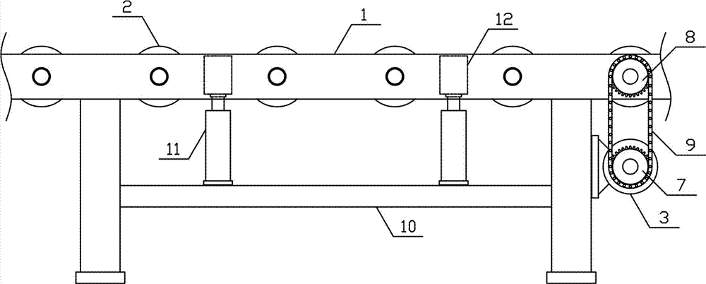
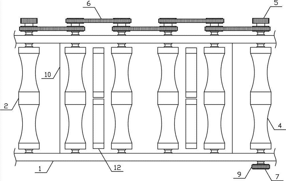
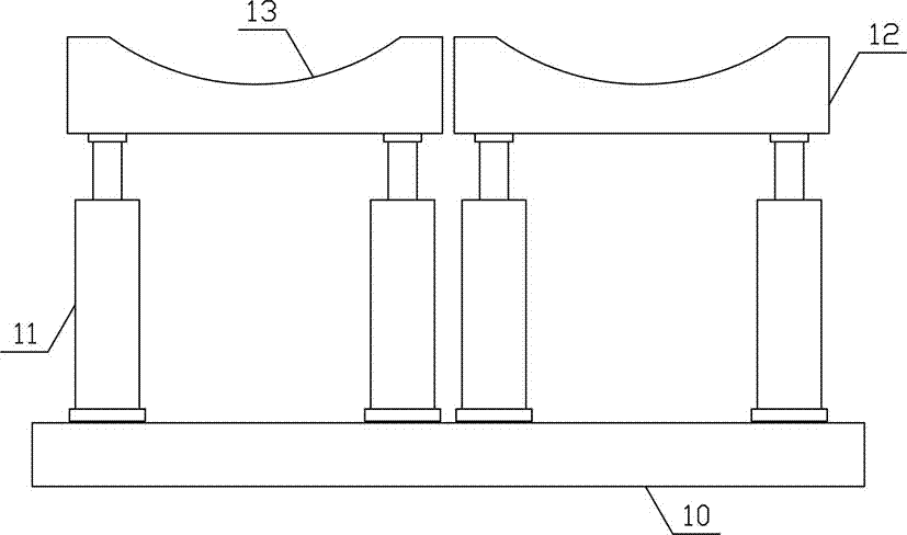
[0013] Such as figure 1 , figure 2 As shown, a pipe conveying and lifting mechanism of the present invention includes a conveying bracket 1, a conveying roller 2, a conveying motor 3 and a pipe lifting mechanism. The two sides are symmetrically provided with arc-shaped duct grooves 4 respectively, and two connecting sprockets 5 are arranged vertically and evenly at one end of the conveying roller 2, and the two adjacent conveying rollers 2 are respectively connected by connecting chain 6, and the conveying motor 3 Horizontally arranged on the lower side of the transmission bracket 1, the output end of the transmission motor 3 is vertically ...


PUM


Abstract

The invention discloses a pipe transferring and lifting mechanism and belongs to the field of transferring mechanical devices. The pipe transferring and lifting mechanism comprises a transferring support, transferring rollers, a transferring motor and a pipe lifting mechanism. The transferring support is sequentially and rotatably connected with the multiple transferring rollers in the horizontal direction, every two adjacent transferring rollers are connected in a transmission mode through a connecting chain, and the upper side of a fixed plate is provided with the pipe lifting mechanism; and the pipe lifting mechanism comprises lifting air cylinders and pipe bearing plates, the two pipe bearing pates are sequentially arranged between every two adjacent transferring rollers in the horizontal direction, and the lifting air cylinders are vertically arranged between the two sides below the pipe bearing plates and fixed plate. According to the pipe transferring and lifting mechanism, structural design is reasonable, pipes can be horizontally and stably lifted in the transferring process, the pipes on the transferring support can be subjected to respective transferring one by one and multiple synchronous transferring according to the machining needs, the quality and efficiency of pipe transferring are improved, and the requirements for pipe production and machining are met.

Description

technical field [0001] The invention belongs to the field of conveying mechanical equipment, and in particular relates to a pipe conveying and lifting mechanism. Background technique [0002] At present, due to the simple, convenient and fast process of pipe processing and production, construction and installation, it has become an important material component in the building structure system, and has been widely used in various fields of national economic construction. Pipes can be used in pipelines, thermal equipment, machinery industry , Petroleum geological drilling, containers, chemical industry and special purposes, especially circular steel pipes are widely used in our industrial production. Fast and efficient processing of pipes is a difficult problem that must be overcome to improve production efficiency. In the field of machinery manufacturing , the pipe needs to be transported horizontally according to the needs. The traditional pipe translation is generally carri...

Claims


Application Information

Patent Timeline
Patent Type & Authority Applications(China)
IPC IPC(8): B65G13/07B65G47/74
CPCB65G13/07B65G47/74B65G2201/0276
Inventor 蔡燕
Owner 蔡燕
Why Eureka
Try Eureka