Supercharge Your Innovation With Domain-Expert AI Agents!

Honeycomb structure

A honeycomb structure and honeycomb technology, applied in the direction of gas treatment, dispersed particle filtration, metal/metal oxide/metal hydroxide catalyst, etc., can solve the problems of driving performance impact, increase pressure loss, etc., and achieve anti-purification performance The effect of reducing and suppressing the rise

Active Publication Date: 2017-08-22
NGK INSULATORS LTD
View PDF6 Cites 5 Cited by
  • Summary
  • Abstract
  • Description
  • Claims
  • Application Information

AI Technical Summary

Problems solved by technology

Here, if the above-mentioned trapping filter is installed on the gasoline engine, there is a possibility that the pressure loss will increase and the running performance will be affected.

Method used


Image

  • Honeycomb structure
  • Honeycomb structure
  • Honeycomb structure

Examples


Embodiment Construction

[0028] Hereinafter, embodiments of the honeycomb structure of the present invention will be described in detail with reference to the drawings. In addition, the honeycomb structure of the present invention is not particularly limited to the following embodiments, and various design changes, corrections, improvements, etc. can be added as long as they do not deviate from the gist of the present invention.

[0029] [1]Honeycomb structure

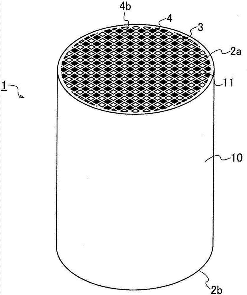
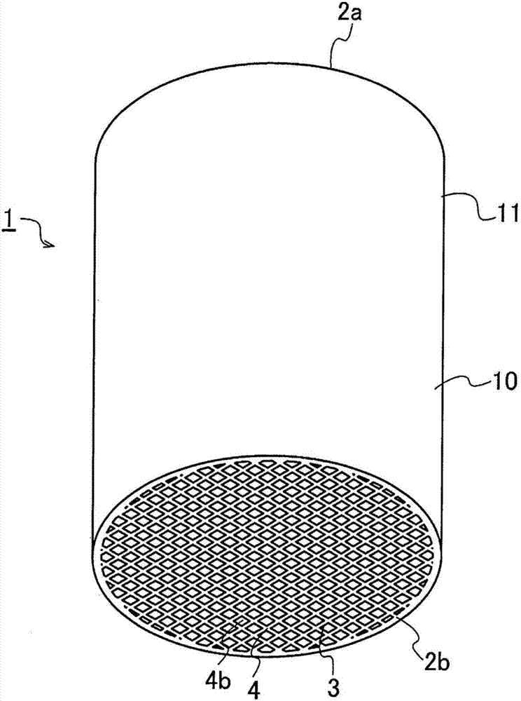
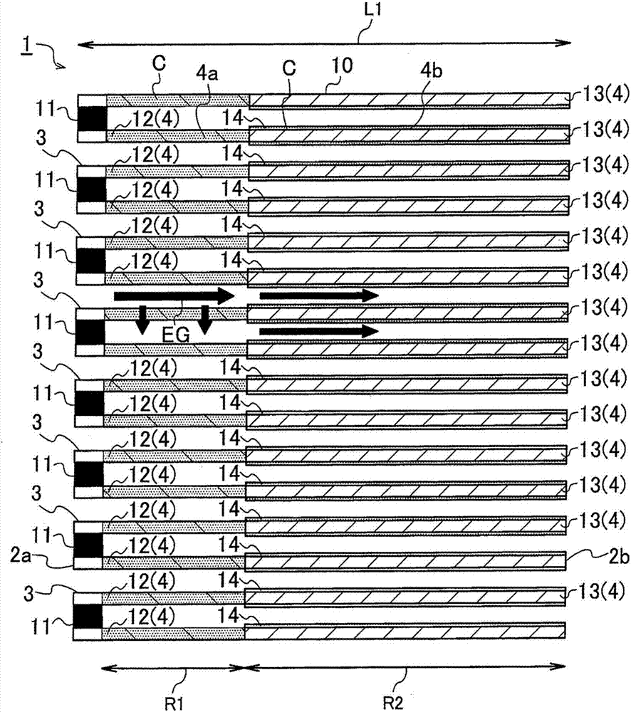
[0030] mainly as figure 1 as well as figure 2 As shown, the honeycomb structure 1 of the present embodiment is mainly composed of a substantially columnar honeycomb base material 10 having a porous lattice shape made of a ceramic material to define a plurality of cells 3 . The partition wall 4, the plurality of compartments 3 extend from one end face 2a to the other end face 2b of the honeycomb base material 10; The compartment 3 of the end face 2a is sealed.

[0031] For the one-side plugging portion 11 of the honeycomb structure 1 of th...


PUM


Abstract

An objective of the invention is to provide a honeycomb structure which can restain pressure loss, increase contact possibility of waste gas and a catalyst, and develop good waste gas purification performance. The honeycomb structure includes a honeycomb substrate having porous partition walls defining a plurality of cells extending from one end face to the other end face, and one-side plugging portions configured to plug the cells in the one end face in accordance with a predetermined arrangement standard, and the partition walls include catalyst impregnated partition walls formed in a first region of a predetermined length extending from the one end face in which the one-side plugging portions are provided, along an axial direction of the honeycomb substrate and formed by impregnating a catalyst into partition wall inner portions, and catalyst layer partition walls formed in a second region of a predetermined length extending from the other end face along the axial direction of the honeycomb substrate and having catalyst layers which coat partition wall surfaces with the catalyst in the form of layers.

Description

technical field [0001] The present invention relates to a honeycomb structure. More specifically, it relates to a honeycomb structure that is used in an exhaust gas purification device for purifying exhaust gas from a gasoline engine and that can prevent a reduction in the purification performance of the exhaust gas. Background technique [0002] In recent years, in response to various demands such as resource saving and energy saving, the development of engines that suppress the consumption of fossil fuels such as gasoline, further suppress the generation of exhaust gas, and exhibit low fuel consumption performance has been promoted. In particular, among gasoline engines generally used as a driving source for automobiles, in order to meet the above-mentioned demand for lower fuel consumption, the development of direct-injection gasoline engine technology in which gasoline is directly injected into cylinders and driven has been advanced. [0003] Direct-injection gasoline e...

Claims


Application Information

Patent Timeline
Patent Type & Authority Applications(China)
IPC IPC(8): F01N3/28
CPCF01N3/101F01N3/2803F01N2510/068B01D46/2474B01D46/2482B01J35/57B01D53/9445B01D2255/9032B01D2255/9155B01D2258/012B01J37/0244B01J23/40B01D2255/915Y02T10/12B01J35/19B01J35/56B01D53/945B01J37/0201F01N3/2842
Inventor 青木崇志
Owner NGK INSULATORS LTD
Features
  • R&D
  • Intellectual Property
  • Life Sciences
  • Materials
  • Tech Scout
  • Unparalleled Data Quality
  • Higher Quality Content
  • 60% Fewer Hallucinations
Learn More