Eureka AIR delivers breakthrough ideas for toughest innovation challenges, trusted by R&D personnel around the world.

Exhaust gas purification system for internal combustion engine

A technology for exhaust purification and internal combustion engines, applied to internal combustion piston engines, exhaust devices, exhaust treatment, etc., can solve the problems of reduced vehicle mountability, reduced degree of freedom of exhaust purification systems, and increased manufacturing costs, achieving improved freedom degree of effect

Inactive Publication Date: 2013-01-23
TOYOTA JIDOSHA KK
View PDF8 Cites 0 Cited by
  • Summary
  • Abstract
  • Description
  • Claims
  • Application Information

AI Technical Summary

Problems solved by technology

In this case, a method of adopting the structure disclosed in the above-mentioned Patent Document 1 is conceivable, but the degree of freedom in the layout of the exhaust purification system is reduced, so there is a possibility of causing a decrease in vehicle mountability and an increase in manufacturing cost.

Method used


Image

  • Exhaust gas purification system for internal combustion engine
  • Exhaust gas purification system for internal combustion engine
  • Exhaust gas purification system for internal combustion engine

Examples


Embodiment 1

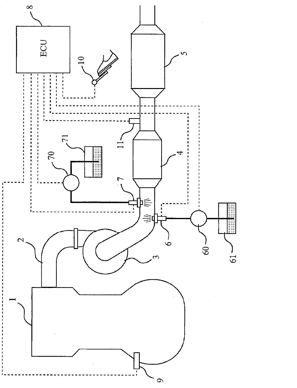
[0040] First, based on Figure 1 to Figure 4 A first embodiment of the present invention will be described. figure 1 It is a diagram showing a schematic configuration of an exhaust system of an internal combustion engine to which the present invention is applied. figure 1 The internal combustion engine shown is a compression-ignition internal combustion engine (diesel engine), but it could also be a spark-ignition internal combustion engine (gasoline engine).

[0041] figure 1 In the internal combustion engine 1, an exhaust passage 2 is connected. The exhaust passage 2 is a passage through which gas (exhaust gas) flowing out of the cylinders of the internal combustion engine 1 flows. A turbine 3 of a centrifugal supercharger (turbocharger) is arranged in the middle of the exhaust passage 2 . An exhaust purification device 4 is arranged in the exhaust passage 2 downstream of the turbine 3 .

[0042] The exhaust purification device 4 accommodates a selective reduction catalys...

Embodiment 2

[0083] Second, based on Figure 5 A second embodiment of the present invention will be described. Here, configurations different from those of the first embodiment described above will be described, and descriptions of the same configurations will be omitted.

[0084] The difference between this embodiment and the first embodiment described above is that a burner 12 is added to the exhaust passage 2 between the turbine 3 and the exhaust purification device 4 . The burner 12 is a device for combusting secondary air supplied from the air pump 120 and fuel supplied from the first pump 60 .

[0085] The combustion chamber 12 is provided with an unillustrated spark plug, and the secondary air and fuel are combusted by the operation of the spark plug. The gas (combustion gas) combusted by the burner 12 is introduced into the exhaust passage 2 through the discharge pipe 121 . In addition, in Figure 5 In the example shown, the burner 12 and the fuel addition valve 6 share the fir...


PUM


Abstract

Disclosed is an exhaust gas purification system for an internal combustion engine, which comprises a selective reduction type catalyst placed in an exhaust gas passage in the internal combustion engine and an addition unit for supplying an ammonia-derived reducing agent to the selective reduction type catalyst, and in which the flexibility of the layout thereof can be improved without deteriorating the reduction capability of a nitrogen oxide. The exhaust gas purification system for an internal combustion engine is so adapted that a hydrocarbon is supplied to the selective reduction type catalyst simultaneously with the ammonia-derived reducing agent, thereby generating a reducing agent that cannot be oxidized readily with a noble metal catalyst.

Description

technical field [0001] The present invention relates to an exhaust gas purification system of an internal combustion engine, in particular to a system capable of treating nitrogen oxides (NO x ) Exhaust purification system of the reduced catalyst. Background technique [0002] There is known an SCR (SCR: Selective Catalytic Reduction, selective reduction catalyst) system that includes a selective reduction catalyst disposed in an exhaust passage of an internal combustion engine, and an exhaust gas disposed upstream of the selective reduction catalyst. The reducing agent addition valve of the passage is used to add the compound or composition derived from ammonia through the reducing agent addition valve. [0003] In recent years, along with the tightening of emission regulations, it is necessary to add an oxidation catalyst and a particulate filter to the SCR system. Therefore, a system has been proposed in which a fuel addition valve, an oxidation catalyst, a particulate ...

Claims


Application Information

Patent Timeline
Patent Type & Authority Applications(China)
IPC IPC(8): F01N3/08
CPCF01N2900/1602F01N2610/03F01N2560/06Y02T10/24F01N3/2033F01N13/02Y02T10/26F01N3/208F01N2900/0416F01N2610/02B01D53/90B01D53/9409B01D53/9495B01D2251/2062F01N13/009Y02T10/12
Inventor 利冈俊祐广田信也伊藤和浩福田光一朗见上晃
Owner TOYOTA JIDOSHA KK
Why Eureka
Eureka Blog
Learn More