LCM liquid crystal display module structure which prevents backlight film from displacement

A liquid crystal display module and backlight module technology, applied in optics, nonlinear optics, instruments, etc., can solve problems such as easy scratches, easy scratches on the light-emitting surface of the light guide plate 4, and affect the display effect of the product, so as to avoid white spots And bright edge, improve the effect of reliability

Pending Publication Date: 2017-08-22
SHENZHEN K&D TECHONOLOGY
View PDF7 Cites 7 Cited by
  • Summary
  • Abstract
  • Description
  • Claims
  • Application Information

AI Technical Summary

Problems solved by technology

[0003] At present, the structure of the traditional LCM liquid crystal display module is as follows: Figure 1 to Figure 3 As shown, it generally includes a FOG liquid crystal display 1, a backlight film material 2, a plastic frame 3, a light guide plate 4, a reflective sheet 5 and a metal back plate 6, the light inlet of the light guide plate 4 is provided with a light bar LB41, and the backlight film material 2 includes The upper brightness enhancement sheet 21, the lower brightness enhancement sheet 22 and the lower diffusion sheet 23, the backlight film material 2 is generally provided with an ear 201 on the left and right sides and fixed in the plastic frame groove 31 of the plastic frame 3; when the LCM liquid crystal display module is vibrating, falling or During the roller test, the backlight film material 2 is easy to move up, down, left, and right in the plastic frame groove 31 and the film materials are displaced, and the materials rub against each other. The back coating of the upper brightness enhancement sheet 21 is easy to scratch the lower brightness enhancement sheet 22; The light guide plate 4 is rubbed, and the light-emitting surface of the light guide plate 4 is easily scratched. In the end, the LCM liquid crystal display module will display white spots or bright edges, which will affect the display effect of the product.

Method used


Image

  • LCM liquid crystal display module structure which prevents backlight film from displacement
  • LCM liquid crystal display module structure which prevents backlight film from displacement
  • LCM liquid crystal display module structure which prevents backlight film from displacement

Examples


Embodiment Construction

[0021] The preferred embodiments provided by the present invention will be specifically described according to the accompanying drawings.

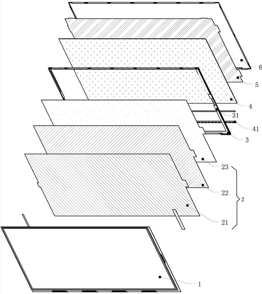
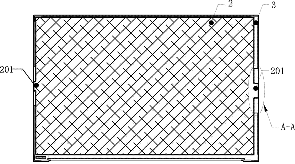
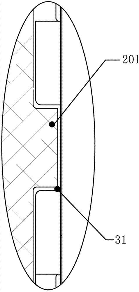
[0022] Figure 4 to Figure 7 , is a schematic diagram of the structure of an LCM liquid crystal display module that prevents the displacement of the backlight film material provided by the present invention. Such as Figure 4 to Figure 7 As shown, the structure of the LCM liquid crystal display module includes a FOG liquid crystal display 10, a plastic frame 20 for placing the FOG liquid crystal display 10, and a backlight module 30 located at the back of the FOG liquid crystal display 10. The backlight of the backlight module 30 is A metal back plate 40 is provided for supporting and protecting.

[0023] The backlight module 30 includes a light guide plate 31, the back of the light guide plate 31 is provided with a reflective sheet 32, the light incident side of the light guide plate 31 is provided with a light bar LB311, and the front ...


PUM


Abstract

The invention provides an LCM liquid crystal display module structure which prevents backlight film from displacement. The LCM liquid crystal display module structure comprises an FOG liquid crystal display screen, a glue frame used for placing the FOG liquid crystal display screen and a backlight module arranged at the back of the FOG liquid crystal display screen, the back of the backlight module is provided with a metal backboard which achieves a support and protection effect, and the backlight module comprises a light guide plate, the back of the light guide plate is provided with a reflecting sheet, the light incidence side face of the light guide plate is provided with an LB, the front of the light guide plate is provided with a backlight film material, the backlight film material is installed on the glue frame, the left side of the backlight film material is provided with one left side fixed lug, the right side of the backlight film material is provided with at least one right side fixed lug, the portion corresponding to the glue frame is provided with a positioning groove used for placing the left side fixed lug and right side fixed lug, the right side fixed lug is provided with a fixed hole, and the positioning groove at the right side of the glue frame is provided with a positioning column matched with the fixed hole. Compared with the prior art, according to the LCM liquid crystal display module structure which prevents the backlight film from displacement, matching between the fixed hole and the positioning column is utilized to make the positioning groove positioned into the glue frame, the occurrence of displacement and deviation of the backlight film material is prevented, and the occurrence of the phenomena of white spots and bright edges is avoided.

Description

technical field [0001] The invention relates to the field of liquid crystal display, in particular to an LCM liquid crystal display module structure for preventing backlight film material from shifting. Background technique [0002] LCM liquid crystal display replaces the traditional CRT cathode ray tube display because of its clear and delicate image, no flicker, no eye injury, no radiation, low power consumption, lighter and thinner, and many other advantages, and is favored by consumers. At present, it is widely used in electronic watches, mobile phones, PDAs, handheld game consoles, learning machines, GPS navigators, digital cameras, digital video cameras, computer monitors and televisions. It is also used in automotive, medical, military and other fields with high reliability requirements. Among them, the better structural design and construction technology can save more energy in daily applications, better protect the liquid crystal display from the influence and dama...

Claims


Application Information

Patent Timeline
Patent Type & Authority Applications(China)
IPC IPC(8): G02F1/13357
CPCG02F1/133608
Inventor 陈永求查小龙吴心亮胡育源周苏令
Owner SHENZHEN K&D TECHONOLOGY
Why Eureka
Try Eureka