Lead frame automatic chip loading machine

A technology of lead frame and chip loading machine, which is applied in the manufacture of electrical components, electric solid devices, semiconductor/solid device, etc., and can solve problems affecting the welding quality of chips and lead frames, lack of heating and oxidation protection of lead frames, etc.

Active Publication Date: 2017-08-22
无锡明祥电子有限公司
View PDF9 Cites 27 Cited by
  • Summary
  • Abstract
  • Description
  • Claims
  • Application Information

AI Technical Summary

Problems solved by technology

[0004] In order to better combine the internal circuit lead-out of the chip with the external lead, it is usually fixed by soft solder welding. However, if the welding process is performed in the above-mentioned track mechanism, it lacks the heating and oxidation protection of the lead frame. Affects the soldering quality of chips and leadframes

Method used


Image

  • Lead frame automatic chip loading machine
  • Lead frame automatic chip loading machine
  • Lead frame automatic chip loading machine

Examples


Embodiment Construction

[0043] The present invention will be described in further detail below in conjunction with the accompanying drawings.

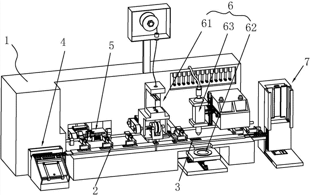
[0044] as attached figure 1 The shown lead frame automatic chip loading machine includes a frame 1, a feeding device 4, a rail conveying device 5, a welding device 6 and an automatic chip loading device 7 arranged on the frame 1 in sequence. When working: first, the lead frame 100 is placed in the feeding device 4 and is loaded from the feeding device 4 to the rail conveying device 5; then, the rail conveying device 5 sends the lead frame 100 from one end of the feeding device 4 to the automatic loading device. One end of the chip device 7; wherein, the welding device 6 is located between the feeding device 4 and the automatic chip loading device 7, in order to complete the welding of the chip on the lead frame 100; finally, the lead frame 100 that has been welded is sent through the rail conveying device 5 into the automatic film loading device 7 for automa...


PUM


Abstract

The invention discloses a lead frame automatic chip loading machine. The key points of the technical scheme are that the lead frame automatic chip loading machine comprises a rack and a material loading device, a track conveying device, a welding device and an automatic chip loading device which are arranged on the rack in turn. The track conveying device comprises conveying tracks which are connected between the material loading device and the automatic chip loading device, a cover shell which closely covers on the conveying tracks and a push mechanism which is used for pushing a lead frame along the conveying tracks to the automatic chip loading device from the material loading device. The upper surface of the cover shell is provided with material feeding grooves and a welding groove which are communicated with the internal part of the cover shell. The material feeding grooves are arranged along the conveying direction of the lead frame and can be stretched into by the push mechanism to push the lead frame. The welding groove is arranged below the welding device and can be used for the welding device to perform welding operation. A segment of conveying tracks arranged in front of the welding device is provided with a heating plate and a gas supply device used for providing protective gas to the inside of the cover shell. Loss of heat can be reduced by the cover shell, and the protective gas is inflated and then heating oxidation of the lead frame can be reduced.

Description

technical field [0001] The invention relates to the field of lead frame chip welding, in particular to an automatic chip loading machine for lead frames. Background technique [0002] The lead frame is the carrier of the integrated circuit chip. It is a key structural part that realizes the electrical connection between the lead-out end of the chip's internal circuit and the outer lead by means of bonding materials (gold wire, aluminum wire, copper wire) to form an electrical circuit. When it comes to the bridge function of connecting with external wires, most semiconductor integrated blocks need to use lead frames, which are important basic materials in the electronic information industry. Most of the chips on it are fixed in the lead frame by welding. [0003] At present, the Chinese patent with the notification number CN102315133A discloses a frame conveying system of an integrated circuit chip loader, which mainly includes a feeding mechanism, a rail mechanism, a feedin...

Claims


Application Information

Patent Timeline
Patent Type & Authority Applications(China)
IPC IPC(8): H01L21/67H01L21/60
CPCH01L21/67144H01L24/74H01L24/78
Inventor 袁伟候士宝王安云
Owner 无锡明祥电子有限公司
Why Eureka
Try Eureka