Novel centrifugal rotor oil filtering machine

A centrifugal rotor and oil filter technology, which is applied in centrifuges and other directions, can solve problems such as difficulty in increasing the rotor speed, affecting the use effect, deformation of the rotor shell, etc., and achieve good dynamic balance, good oil filtering effect, and increased speed. Effect

Inactive Publication Date: 2017-08-25
孙亮熙
View PDF5 Cites 2 Cited by
  • Summary
  • Abstract
  • Description
  • Claims
  • Application Information

AI Technical Summary

Problems solved by technology

The centrifugal rotor oil filter has the following problems in use: when the oil pressure is low, the driving force is insufficient, the rotor speed is low, and the oil filtering effect is poor; when the oil pressure is high, the outward expansion force generated by the pressure makes the rotor dynamic balance Poor, the rotor shell is deformed, oil leaks outward, and the rotor speed is difficult to increase, which affects the use effect

Method used


Image

  • Novel centrifugal rotor oil filtering machine
  • Novel centrifugal rotor oil filtering machine
  • Novel centrifugal rotor oil filtering machine

Examples


specific Embodiment approach 1

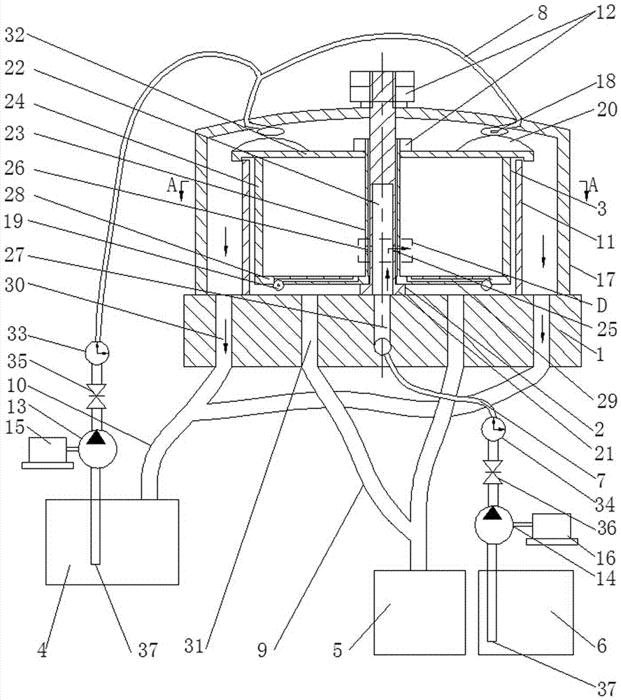
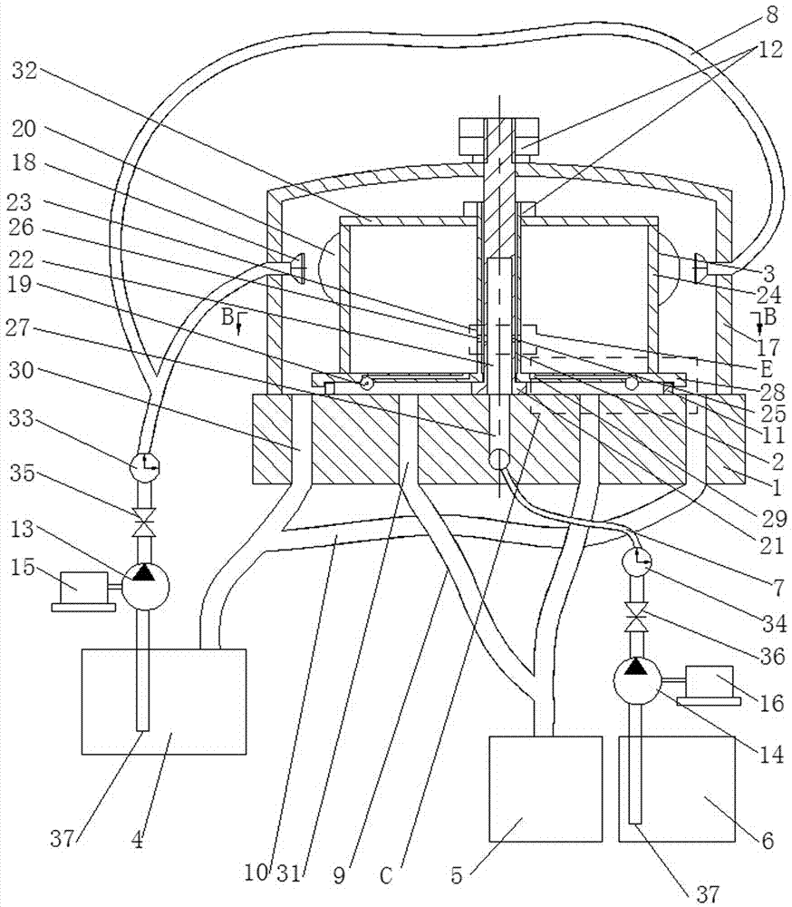
[0019] Specific implementation mode one: as figure 1 , figure 2 and Image 6 As shown, this embodiment discloses a new centrifugal rotor oil filter, which consists of a base 1, a central shaft 2, a rotor 3, a working hydraulic oil tank 4, a cleaned oil tank 5, and an uncleaned oil tank 6. Uncleaned pressure oil pipe 7, cleaned oil return pipe 9, outer cover 17, two rotor nozzles 19, two oil pumps, two motors and at least two lock nuts 12, the two oil pumps They are oil pump one 13 and oil pump two 14 respectively, and the two motors are motor one 15 and motor two 16 respectively; it is characterized in that: the novel centrifugal rotor oil purifier also includes an oil-separating sleeve 11, a high-pressure working hydraulic pressure Oil pipe 8, working hydraulic oil return pipe 10, multiple outer cover nozzles 18 and multiple blades 20;

[0020]One end of the central shaft 2 is provided with a boss 21, the boss 21 of the central shaft 2 is detachably connected to the upper...

specific Embodiment approach 2

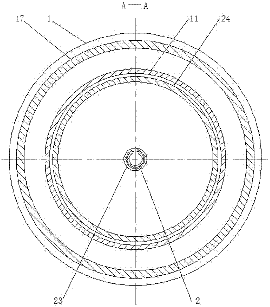
[0021] Specific implementation mode two: as figure 1 As shown, this embodiment is a further description of Embodiment 1. The rotor 3 includes a central sleeve 23, a housing 24, a bottom cover 28 and a top cover 32. The lower end of the central sleeve 23 is connected to the bottom The upper surface of the cover 28 is fixedly connected, the middle part of the bottom cover 28 is provided with a shaft hole, and the outer shell 24 is sleeved on the outside of the central sleeve 23, and the lower end of the shell 24 is fixedly connected with the upper surface of the bottom cover 28. 24. The center sleeve 23 and the shaft hole are set coaxially. The top cover 32 is fixed on the upper surface of the shell 24. The middle part of the top cover 32 is provided with a sleeve passing hole. The outer edge of the top cover 32 An outer edge is provided downward, and the upper end of the oil-separating sleeve 11 is arranged inside the outer edge of the top cover 32 .

specific Embodiment approach 3

[0022] Specific implementation mode three: as figure 1 As shown, this embodiment is a further description of Embodiment 1. The plurality of blades 20 are evenly arranged along the outer periphery of the top surface of the rotor 3 , and each blade 20 is arranged along the radial direction of the rotor 3 .


PUM


Abstract

The invention relates to a novel centrifugal rotor oil filtering machine, and belongs to the field of impurity pollution oil centrifugal purification treatment. A rotor is installed on the outer side of a center shaft in a sleeving manner, an oil isolating sleeve is installed on the outer side of the rotor in a sleeving manner, an outer cover covers the exterior of the rotor, blades are arranged at the top end face of the rotor, outer cover spraying heads are arranged nearby the inner top face of the outer cover and are communicated with a high-pressure working hydraulic oil pipe, the spraying direction of the multiple outer cover spraying heads is coincident with the rotating direction of the rotor, and jetting is carried out in the tangential direction of the rotor; a center hole is communicated with an inner cavity of the rotor through a first transition oil hole and a second transition oil hole, the center hole of the center shaft is communicated with an oil inlet channel in a base, one end of a cleaned pressure oil way arranged inside a rotor bottom cover is communicated with the inner cavity of the rotor, and the other end of the pressure oil way is provided with a rotor spraying head; and the jetting direction of the rotor spraying head is opposite to the rotating direction of the rotor, and jetting is carried out in the tangential direction of the rotor. The novel centrifugal rotor oil filtering machine is used for centrifugal purification treatment of oil such as cutting oil, line drawing oil, circulatory system oil, anti-rusting oil, flushing oil and cold heading oil which are easily polluted by impurities.

Description

technical field [0001] The invention relates to an oil filter, in particular to a novel centrifugal rotor oil filter, which belongs to the field of centrifugal purification treatment of impurity polluted oil. Background technique [0002] In the existing centrifugal rotor oil filter, a double-spray nozzle is arranged on the rotor body, and the pressure generated by the cleaned oil entering the interior of the rotor makes the rotor nozzle spray oil outward to provide its driving force. The centrifugal rotor oil filter has the following problems in use: when the oil pressure is low, the driving force is insufficient, the rotor speed is low, and the oil filtering effect is poor; when the oil pressure is high, the outward expansion force generated by the pressure makes the rotor dynamic balance Poor, the rotor shell is deformed, oil leaks outward, and the rotor speed is difficult to increase, which affects the use effect. Contents of the invention [0003] The purpose of the ...

Claims


Application Information

Patent Timeline
Patent Type & Authority Applications(China)
IPC IPC(8): B04B9/06B04B5/12B04B13/00
CPCB04B5/12B04B9/06B04B13/00
Inventor 孙亮熙
Owner 孙亮熙
Why Eureka
Try Eureka