Casting die avoiding press shell interior shrinkage porosity

A technology of casting mold and shrinkage porosity, which is applied in the field of metal casting and casting, can solve the problems of shrinkage porosity in the center of the casting, thick structure, long feeding distance, etc., to prevent air leakage of the casting and prevent shrinkage on the surface of the casting The effect of loosening and eliminating shrinkage

Active Publication Date: 2017-08-25
CRRC CHANGZHOU AUTO PARTS CO LTD +1
View PDF7 Cites 7 Cited by
  • Summary
  • Abstract
  • Description
  • Claims
  • Application Information

AI Technical Summary

Problems solved by technology

However, with the continuous development of turbocharger technology, some pressure shells with special structures have appeared (for example, the middle position is thick and relatively isolated, and the wall thickness of the casting is thicker), which actually shows that this type of pressure shell has passed the traditional casting process. It cannot completely eliminate internal and pipe wall shrinkage porosity, because under the conditions of traditional casting technology, the internal structure of this type of pressure shell is thick during the filling and solidification process, and the distance to be fed is relatively long. The medium feeding channel is often solidified before the thick part in the center of the casting. As a result, the riser cannot effectively perform its feeding function on the thick part in the center of the casting, resulting in shrinkage defects in the thick part in the center of the casting, which seriously affects the quality of the casting.

Method used


Image

  • Casting die avoiding press shell interior shrinkage porosity
  • Casting die avoiding press shell interior shrinkage porosity
  • Casting die avoiding press shell interior shrinkage porosity

Examples


Embodiment 1

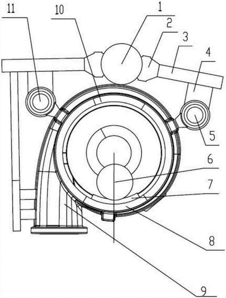
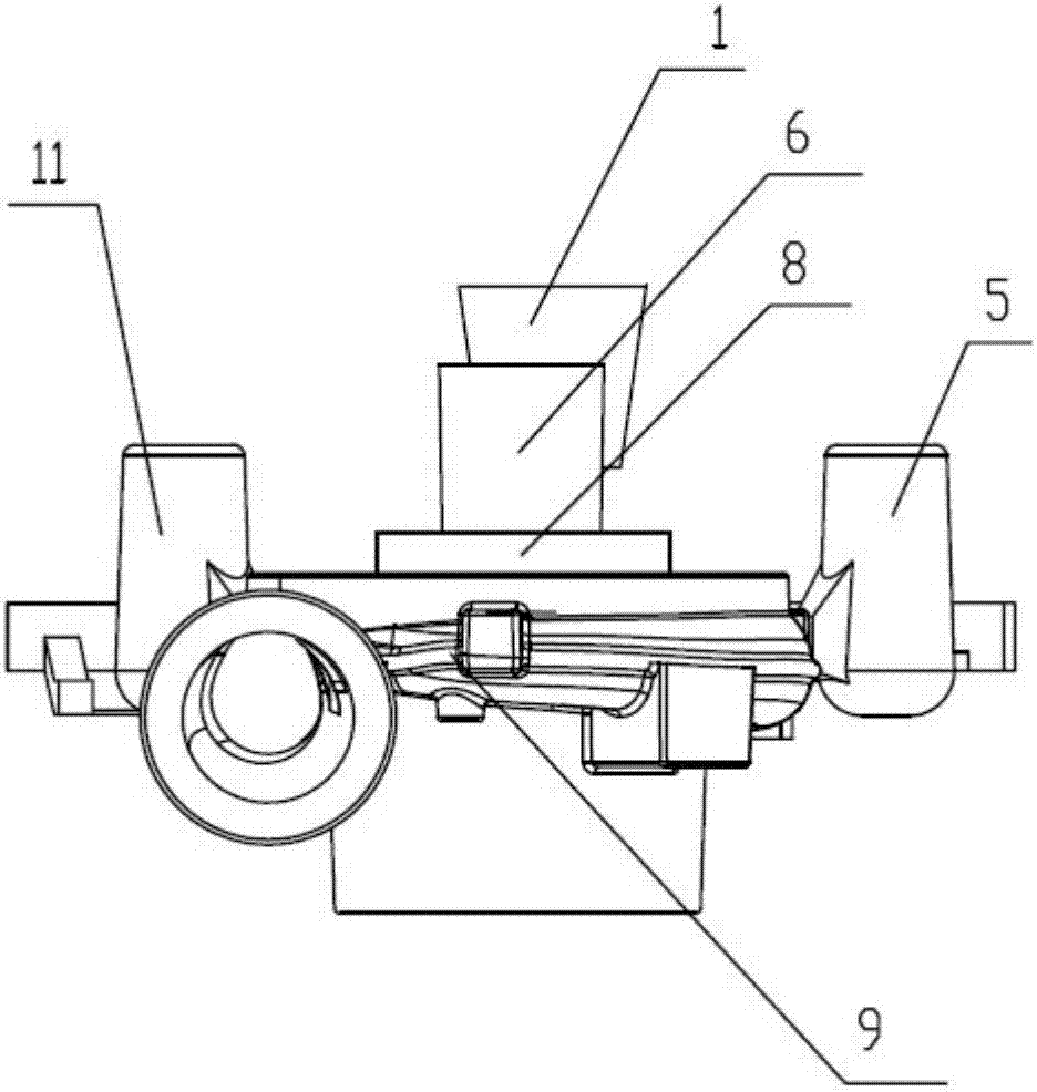
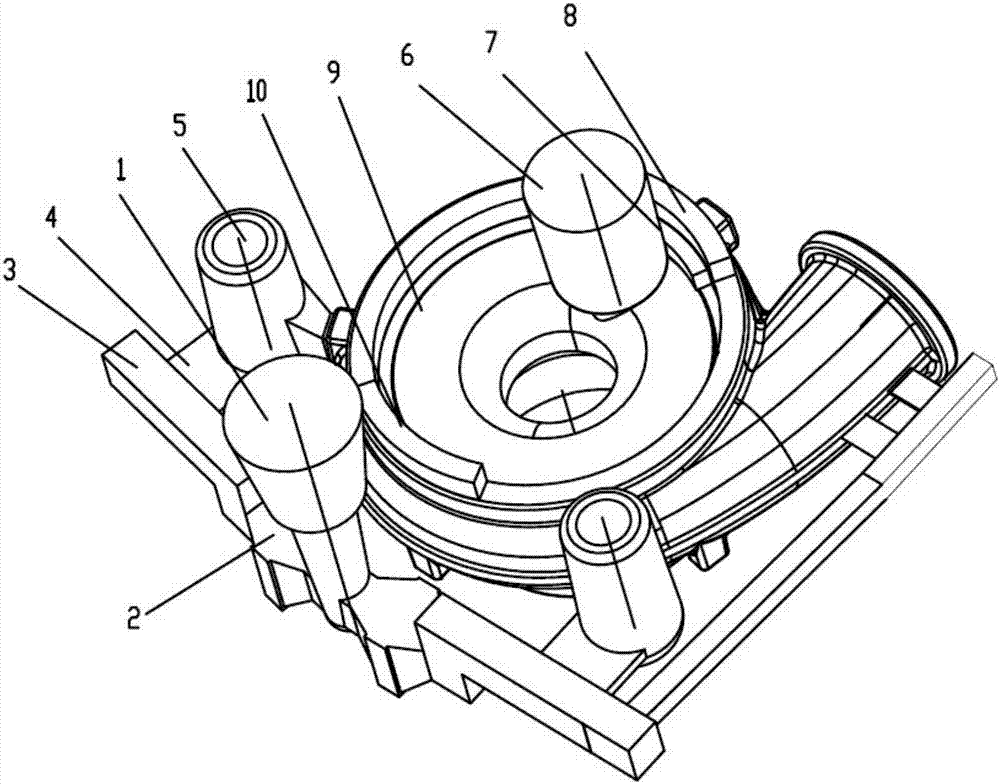
[0014] This embodiment solves the casting mold with shrinkage inside the pressure shell such as figure 1 , 2 , 3, the pressure shell main body mold 9 with the required internal cavity is in the shape of a volute, and the outer side of the pressure shell main body mold 9 away from the outlet of the volute has a vertical runner 1 with an upper end opening, and the vertical runner 1 passes through the The horizontal runners 3 extending to both sides communicate with the two inner runners 4 facing the pressure shell body mold 9 respectively. The filter block 2 is passed between the vertical runner 1 and the horizontal runner 3 . The two inrunners 4 communicate with the radial inlet of the pressure shell main body mold 9 after respectively passing through the inlet risers 5 and 11 opening upward. The angle between the two radial inlets is 120°, and two arc-shaped cold irons 8,10 adjacent to the outer circle on the disc upper surface of the pressure shell body mold 9 are provided ...


PUM


Abstract

The invention relates to a casting die avoiding press shell interior shrinkage porosity, and belongs to the technical field of metal casting. The casting die comprises a volute-shaped press shell body die provided with a needed interior cavity. A vertical pouring gate with the upper end opened is arranged on the outer side of the press shell body die. The vertical pouring gate communicates with two inner pouring gates facing the press shell body die through a horizontal pouring gate extending towards the two sides. The inner pouring gates pass through an inlet end dead head with an upward opening and then communicate with radial inlets of the press shell body die. Two shape following chillers located on the upper surface of the press shell body die disc are arranged between the two radial inlets. The side, away from the vertical pouring gate, of the press shell body die is provided with a heating dead head extending upwards through a shrunk neck, and an arc chiller is arranged between the shrunk neck of the heating dead head and the upper surface of the press shell body die disc. By means of the casting die, maximum-degree feeding can be conducted on the thick and large part in a casting through the dead head, the situation that due to the too large size, a dead head neck is solidified in advance, and the feeding effect of the heating dead head is influenced is avoided, and the situation that shrinkage porosity happens to the wall of a press shell pipe, and air leakage is caused to the casting can be prevented.

Description

technical field [0001] The invention relates to a casting method, in particular to a casting mold for solving shrinkage porosity inside a pressure shell, and belongs to the technical field of metal casting. Background technique [0002] The pressure shell of the conventional structure of the turbocharger adopts the traditional casting process to realize the casting without shrinkage inside the pressure shell, so the requirement of leak detection can basically be completely suppressed. However, with the continuous development of turbocharger technology, some pressure shells with special structures have appeared (for example, the middle position is thick and relatively isolated, and the wall thickness of the casting is thicker), which actually shows that this type of pressure shell has passed the traditional casting process. It cannot completely eliminate internal and pipe wall shrinkage porosity, because under the conditions of traditional casting technology, the internal str...

Claims


Application Information

Patent Timeline
IPC IPC(8): B22C9/08B22C9/24
CPCB22C9/082B22C9/088B22C9/24
Inventor 陈呈祥刘军明刘方平吴俊俊王学青
Owner CRRC CHANGZHOU AUTO PARTS CO LTD
Why Eureka
Try Eureka