Ship

A hull and bow technology, applied in the field of boats with improved hulls

Pending Publication Date: 2017-08-25
珠海横琴琛龙恒远船舶科技有限公司
View PDF7 Cites 1 Cited by
  • Summary
  • Abstract
  • Description
  • Claims
  • Application Information

AI Technical Summary

Problems solved by technology

[0008] In order to reduce the wave-making resistance, the traditional hull design method is to adopt the bulbous bow design, but

Method used


Image

  • Ship
  • Ship
  • Ship

Examples


no. 1 example

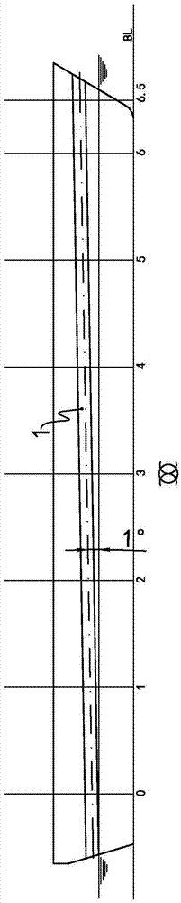
[0036] see figure 1 , this is a schematic diagram of the starboard side of the hull of a small ship. Due to the short length of the ship, only 6.5 stations are used in the figure. It can be seen that there is an inner groove 1 from the bow to the stern on the freeboard, and it is also symmetrical on the invisible port side The set has the same inner groove. The angle α between the centerline of the inner groove 1 and the waterline is shown in figure 1 The center is marked as 1°.

[0037] see figure 2 , it can be seen that the shape of the inner groove 1 at each station, the groove width is the same at each station, the groove depth is at the stern plate, and the same at stations 0 to 5. The groove depth at the post is zero.

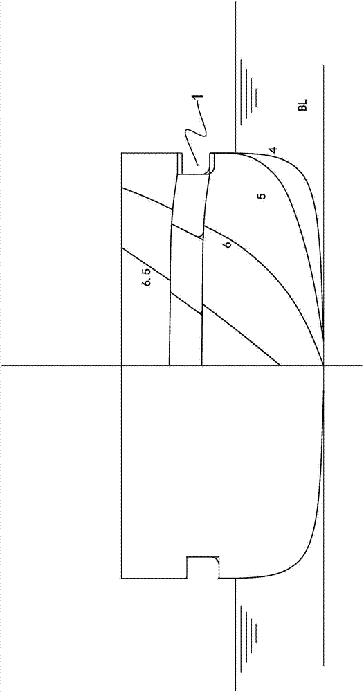
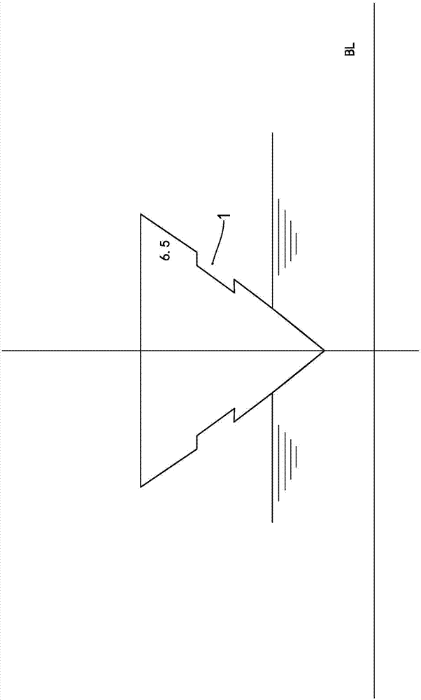
[0038] see image 3 with Figure 4 , visible at station 6.5 and the shape of the inner groove 1 at station 4.

[0039] see Figure 5 with Image 6 , the shape of the internal groove 1 on the hull of the first embodiment can be seen.

no. 2 example

[0041] The following only describes the differences between this example and the previous example, see Figure 7 , the ship type, hull size, and speed of this example are different from those of the previous example. Therefore, the angle α between the centerline of the inner groove 1 and the waterline is shown in Figure 7 The label in is -1°.

no. 3 example

[0043] see Figure 8 , Figure 8 It is a typical cross-sectional schematic diagram of an ocean-going ship, which has a relatively high freeboard. Therefore, in this example, three internal grooves are arranged in parallel on the freeboard to minimize the area of ​​head-on-wave resistance during surfing .


PUM


Abstract

The invention provides a ship and relates to the technical field of ship engineering. The ship comprises a ship body provided with board parts, wherein longitudinal internal grooves are symmetrically formed in left and right freeboards. The ship has the function that the wave-making resistance and/or rough water resistance of the ship body is reduced.

Description

technical field [0001] The present invention relates to a ship and, in particular, to a ship with an improved hull. Background technique [0002] A surface ship is generally composed of a hull and a superstructure. The hull is generally a watertight hull composed of a deck, starboard and bottom sides, and the bottom. The side above the waterline to below the deck is called the freeboard. [0003] When a ship sails on the water and moves in two mediums of air and water, it must encounter the resistance of the air and water to the hull. [0004] Air resistance refers to the reaction force of air on the superstructure and the above water part of the hull. Water resistance refers to the reaction force of water on the underwater part of the hull. The water resistance is further divided into two parts: the still water resistance during still water sailing and the resistance increase value in waves. [0005] First of all, the hull will generate waves during the movement, and the...

Claims


Application Information

Patent Timeline
IPC IPC(8): B63B1/40
CPCB63B1/40Y02A30/30Y02T70/10
Inventor 梁明森
Owner 珠海横琴琛龙恒远船舶科技有限公司
Why Eureka
Try Eureka