Slag removal device for drilling

A technology of slag removal and power device, which is applied in the direction of earthwork drilling, wellbore/well components, etc., can solve the problems of slag removal equipment affecting drilling efficiency, etc., and achieve the effects of saving operation time, improving operation efficiency and reducing operation cost

Pending Publication Date: 2017-08-25
NENGCHENG GRP
View PDF10 Cites 0 Cited by
  • Summary
  • Abstract
  • Description
  • Claims
  • Application Information

AI Technical Summary

Problems solved by technology

[0005] Therefore, the technical problem to be solved by the present invention is to overcome the defect that the slag removal equipment in the prior art must be interrupted before the drilling operation can be used, which affects the drilling efficiency, so as to provide a drilling machine capable of continuous drilling without affecting the drilling efficiency. slag removal device

Method used


Image

  • Slag removal device for drilling
  • Slag removal device for drilling
  • Slag removal device for drilling

Examples


Embodiment 1

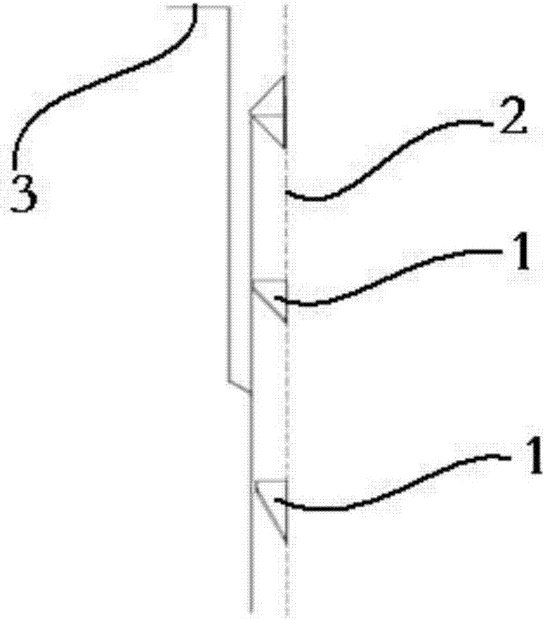
[0040] figure 1 It is a partial structural schematic diagram of a slag removal device for drilling provided in Embodiment 1 of the present invention; figure 2 for figure 1 The top view of the upper-level material lifting mechanism shown; Figure 1-2 As shown, the slag removal device for drilling provided in this embodiment includes a steel cable 2 suitable for connecting an impact hammer at one end, and a wellhead power device connected to the other end of the steel cable 2. The wellhead power device can drive the steel cable 2 to lift or The reciprocating movement of lowering, and several lifting mechanisms 1 arranged on the steel cable 2, several lifting mechanisms 1 are fixedly arranged on the steel cable 2 at intervals from the top of the impact hammer to the wellhead 3, and the lifting mechanism 1 is bucket-shaped The structure includes two sets of side plates 6 arranged in parallel on both sides of the steel cable 2, and a connecting plate arranged between each set of...

Embodiment 2

[0051] As an alternative to the first embodiment, this embodiment provides a slag removal device for drilling. The difference between the lifting mechanism (1) of the slag removal device and the first embodiment is that:

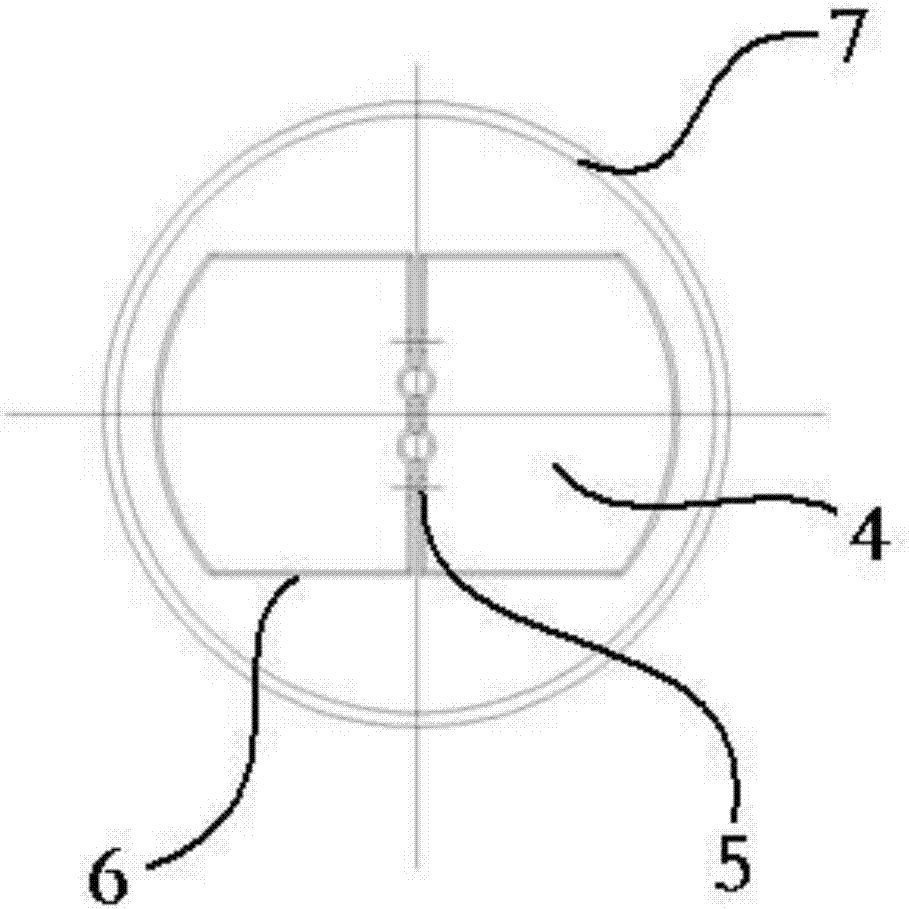
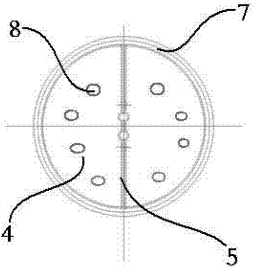
[0052] Such as image 3 As shown, the housing of the lifting mechanism is a bucket-shaped structure with a circular outer contour adapted to the inner contour of the well wall (7), and the cross-section of the second opening at the bottom of the housing is equivalent to the well hole The two D-shaped material receiving plates (4) symmetrically arranged at the second opening can close the entire well hole, and a number of hollow holes (8) are formed on the material receiving plate (4) to form a discharge channel for the reciprocating flow of mud, which can Reducing the resistance suffered by the material lifting mechanism when lifting or falling can also reduce the impact force on the butt joint material plate (4), and avoid damage and fracture of the joint b...

Embodiment 3

[0056] This embodiment, as an alternative to the first embodiment, provides a slag removal device for drilling. The difference between the lifting mechanism of the slag removal device and the first embodiment is that:

[0057] The material lifting mechanism is a shell with a top opening, and several hollow structures are formed on the bottom surface of the shell. Several material lifting mechanisms are fixedly arranged on the steel cable from the top of the impact hammer to the wellhead at intervals, so that from the top of the impact hammer to the wellhead The wellhead forms a continuous mud lifting channel, and a lifting mechanism first introduces the mud from the hollow structure into the shell during the falling process during a lifting cycle, and then rises to lift the mud inside; the lifting mechanism In the next lifting cycle, the upper-level lifting mechanism catches the mud raised by the lifting mechanism and starts to rise. In this way, the mud with high suspension co...


PUM


Abstract

The invention relates to the technical field of slag removal in drilling, in particular to slag removal device for drilling. The device includes a steel rope, a well head power device and a material lifting mechanism, wherein one end of the steel rope is suitable for being connected with a percussion hammer, the well head power device is connected with the other end of the steel rope and drives the steel rope to do reciprocating motion of lifting or lowering, and the material lifting mechanism is arranged on the steel rope. By the adoption of the slag removal device for drilling, the synchronous operation of slag removal and drilling is achieved, the slag removal device for drilling not only saves the working hours and improves the working efficiency but also reduces the working cost, it is unnecessary to arrange machinery and stuff to remove slag, and slag removal device for drilling is convenient, efficient and suitable for popularization and application.

Description

technical field [0001] The invention relates to the technical field of drilling slag removal, in particular to a drilling slag removal device. Background technique [0002] During percussion drilling construction, mud protection walls are often used to prevent hole collapse, suspended cuttings, and safe passage through the quicksand layer. The function of suspended cuttings can prevent cuttings from sinking to the bottom of the hole quickly and prevent buried drilling accidents. As the drilling operation proceeds, because the impact hammer continuously reciprocates through the mud liquid during work, agitates the mud, and the broken cuttings are evenly distributed in the mud, so that the concentration of cuttings in the mud increases gradually. Excessive cuttings concentration in the mud will lead to poor floating effect of cuttings on the one hand, and more importantly, it will hinder the drilling operation of the drilling tool. Therefore, it is necessary to remove cutting...

Claims


Application Information

Patent Timeline
IPC IPC(8): E21B27/02
CPCE21B27/02
Inventor 王斌坚
Owner NENGCHENG GRP
Why Eureka
Try Eureka