Convenient building construction equipment

A kind of building construction and convenient technology, applied in construction, bridge construction, erection/assembly of bridges, etc., can solve the problems of easy arcing, uneven plug force, electric shock accidents, etc., to improve work efficiency, reduce labor, improve The effect of insertion tightness

Inactive Publication Date: 2017-08-25
SHISHI CHUANLANG MACHINERY DESIGN CO LTD
View PDF7 Cites 5 Cited by
  • Summary
  • Abstract
  • Description
  • Claims
  • Application Information

AI Technical Summary

Problems solved by technology

[0002] Building construction refers to the production activities in the implementation stage of engineering construction. It is the construction process of various buildings. During the construction process, most construction equipment needs electricity. Traditional and convenient building construction equipment is usually manually plugged in when using electricity. Unable to realize automatic control operation, there is uneven plugging force through manual plugging by personnel, which may easily lead to damage to the electric head, and at the same time, it is easy to generate electric arcs during plugging and unplugging, resulting in electric shock accidents, which has great potential safety hazards, and the traditional manual plugging There is also the phenomenon of unstable connection in the way of plugging, and the function is single

Method used


Image

  • Convenient building construction equipment
  • Convenient building construction equipment
  • Convenient building construction equipment

Examples


Embodiment Construction

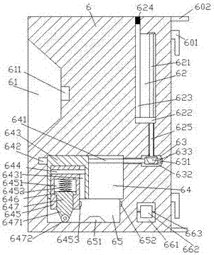
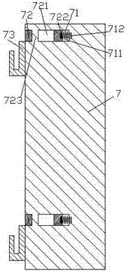
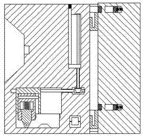
[0026] Such as Figure 1-Figure 8 As shown, a convenient building construction equipment of the present invention includes a power transmission cabinet 6 and a hanger 7. A first sliding connection cavity 64 is provided in the power transmission cabinet 6, and a guide is provided at the bottom end of the first sliding connection cavity 64. Move the sliding connection groove 65, the first sliding connection cavity 64 is provided with a first screw connecting rod 641 deployed left and right, the left end of the first screw connecting rod 641 is connected with the first motor 642, and the first screw connecting rod 641 is connected to the first motor 642. The connecting rod 641 is screwed with a first sliding joint block 643, and the first sliding joint block 643 is provided with a first sliding joint groove 6431, and the first sliding joint groove 6431 is provided with guides for extending left and right. Sliding connecting rod 644, the sliding connecting rod 644 is connected wit...


PUM


Abstract

The invention discloses convenient building construction equipment, which comprises a power transmission cabinet and a hanging bracket, and is characterized in that the power transmission cabinet is internally provided with a first sliding connection cavity, the inner bottom end of the first sliding connection cavity is provided with a movement-guiding sliding connection groove, the first sliding connection cavity is internally provided with a first screw connection rod which is arranged in a transversely expanding manner, the left end of the first screw connection rod is connected with a first motor, the first screw connection rod is matched with a first sliding connection block in a screw connection manner, the first sliding connection block is internally provided with a first sliding connection groove, the first sliding connection groove is internally provided with a movement-guiding sliding connection rod which is arranged in a transversely expanding manner, the movement-guiding sliding connection rod is connected with a second sliding connection block in a matched sliding connection manner, the bottom of the second sliding connection block penetrates into the movement-guiding sliding connection groove and is connected with the movement-guiding sliding connection groove in a matched sliding connection manner, the second sliding connection block is internally provided with a second sliding connection cavity, the second sliding connection cavity is internally provided with a third sliding connection block, the bottom of the third sliding connection block is provided with a first compression spring, the bottom of the third sliding connection block is provided with a pushing sliding connection block which longitudinally penetrates through the bottom end face of the second sliding connection block, the bottom of the pushing sliding connection block is provided with an engagement segment, and the bottom of the engagement segment is provided with a transfer wheel. The building construction equipment is simple in structure, convenient to operate, capable of automatically operating, providing power and plugging, convenient to install and remove and high in safety.

Description

technical field [0001] The invention relates to the field of building construction facilities, in particular to convenient building construction equipment. Background technique [0002] Building construction refers to the production activities in the implementation stage of engineering construction. It is the construction process of various buildings. During the construction process, most construction equipment needs electricity. Traditional and convenient building construction equipment is usually manually plugged in when using electricity. Unable to realize automatic control operation, there is uneven plugging force through manual plugging by personnel, which may easily lead to damage to the electric head, and at the same time, it is easy to generate electric arcs during plugging and unplugging, resulting in electric shock accidents, which has great potential safety hazards, and the traditional manual plugging There is also the phenomenon of unstable connection in the way ...

Claims


Application Information

Patent Timeline
Patent Type & Authority Applications(China)
IPC IPC(8): H01R13/447H01R13/627H01R13/629H01R13/631H01R13/639H01R13/717E01D22/00
CPCH01R13/629E01D22/00H01R13/447H01R13/627H01R13/631H01R13/639H01R13/717
Inventor 范全有
Owner SHISHI CHUANLANG MACHINERY DESIGN CO LTD
Why Eureka
Try Eureka