Device for optically generating radar pulse compression signals

A radar pulse and compressed signal technology, applied in microwave and photonic fields, can solve the problems of high system complexity and high cost, and achieve the effects of large frequency adjustable range, large time-bandwidth product, and stable performance

Active Publication Date: 2017-08-25
EAST CHINA NORMAL UNIV
View PDF8 Cites 19 Cited by
  • Summary
  • Abstract
  • Description
  • Claims
  • Application Information

AI Technical Summary

Problems solved by technology

The disadvantage of this method is that in addition to using an optical modulator to generate two coherent light wavelengths, it also needs to use optical filtering, phase modulation or polarization modulation, etc., resulting in high system complexity and high cost.

Method used


Image

  • Device for optically generating radar pulse compression signals
  • Device for optically generating radar pulse compression signals
  • Device for optically generating radar pulse compression signals

Examples


Embodiment 1

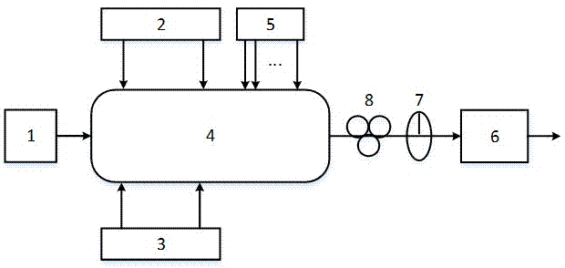
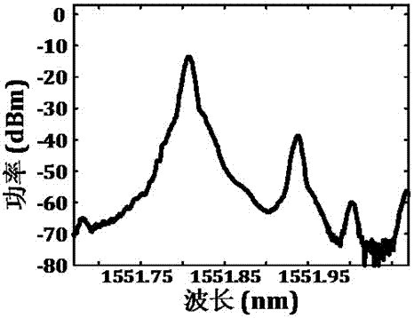
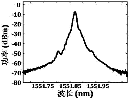
[0045] The frequency of the microwave signal output by the microwave signal source is 8GHz, which drives a sub-dual parallel Mach-Zehnder modulator of the polarization multiplexing dual-parallel Mach-Zehnder modulator. The output spectrum of the sub-dual parallel Mach-Zehnder modulator is shown in figure 2 . The coded signal generator generates a 500Mb / s binary square wave signal or a four-level ladder signal to drive another sub-parallel Mach-Zehnder modulator of the polarization multiplexing dual-parallel Mach-Zehnder modulator, and its output spectrum is shown in image 3 . The output optical signal after the polarizer is figure 2 and image 3 Coupling of optical signals shown, spectrogram see Figure 4 . The output of the photodetector is an 8GHz phase-encoded signal, and the phase information can be recovered by Hilbert transform, see Figure 5 . Change the signal generated by the encoded signal generator into a 128-bit 500Mb / s binary pseudo-random sequence or a q...

Embodiment 2

[0047] The frequency of the microwave signal output by the microwave signal source is 13 GHz, which drives a sub-dual parallel Mach-Zehnder modulator of the polarization multiplexing dual-parallel Mach-Zehnder modulator. The output spectrum of the sub-dual parallel Mach-Zehnder modulator can be found in Figure 7 . The coded signal generator generates a 500Mb / s binary square wave signal or a four-level ladder signal to drive another sub-parallel Mach-Zehnder modulator of the polarization multiplexing dual-parallel Mach-Zehnder modulator, and its output spectrum is shown in Figure 8 . The output optical signal after the polarizer is Figure 7 and Figure 8 Coupling of optical signals shown, spectrogram see Figure 9 . The output of the photodetector is a 13GHz phase-encoded signal, and the phase information can be recovered by Hilbert transform, see Figure 10 . Change the signal generated by the encoded signal generator into a 128-bit 500Mb / s binary pseudo-random sequen...


PUM


Abstract

The invention discloses a device for optically generating radar pulse compression signals. The device comprises a laser, a coding signal generator, a microwave signal generator, a polarization multiplexing double-parallel Mach-Zehnder modulator, a direct-current power supply, a photoelectric detector, a polarizer and a polarization controller; and, by utilization of the frequency-shifting characteristic and the phase modulation characteristic of the polarization multiplexing double-parallel Mach-Zehnder modulator, after being coupled through the polarizer, polarization orthogonal modulated optical carrier signals and unmodulated optical first-order sideband signals output by the polarization multiplexing double-parallel Mach-Zehnder modulator are detected through the photoelectric detector, so that phase coded or linearly frequency-modulated radar pulse compression signals can be generated. On the basis of the integrated modulator structure, the device disclosed by the invention is simple in system composition and steady in performance; and, the following disadvantages can be overcome: the traditional manner of generating pulse compression signals in the electric domain is limited by the rate and the bandwidth of an electronic device; high-frequency signals are generated difficultly or cannot be generated; the time-bandwidth product is limited; the reconfigurability and the frequency adjustability of the system are poor, etc.

Description

technical field [0001] The invention relates to the field of microwave technology and the field of photon technology, in particular to a device for optically generating radar pulse compression signals. Background technique [0002] With the continuous development of radar technology, the requirements for radar operating range, resolution capability and measurement accuracy are getting higher and higher. The initial pulse radar transmits a pulse with a fixed carrier frequency, and its distance resolution is inversely proportional to the width of the transmitted pulse. To increase the operating distance, it is required to increase the emission pulse width, which will inevitably reduce the distance resolution. Since the matching filter theory was proposed in the 1940s and the radar ambiguity principle was proposed by Woodward in the early 1950s, people realized that the radar system should have a long range, high range and speed measurement accuracy, and good distance and spee...

Claims


Application Information

Patent Timeline
Patent Type & Authority Applications(China)
IPC IPC(8): H04B10/556H04B10/532H04J14/06
CPCH04B10/532H04B10/5561H04B10/5563H04J14/06
Inventor 陈阳
Owner EAST CHINA NORMAL UNIV
Why Eureka
Try Eureka