Mechanical derusting equipment for wire rods

A technology for mechanical rust removal and wire rod application in metal processing equipment, grinding/polishing equipment, grinding racks, etc., which can solve the problems of poor rust removal effect and low degree of automation.

Pending Publication Date: 2017-08-29
葛云杰
View PDF15 Cites 2 Cited by
  • Summary
  • Abstract
  • Description
  • Claims
  • Application Information

AI Technical Summary

Problems solved by technology

At present, the mechanical derusting method for wire rods is still rarely adopted on a large scale, mainly due to the low degree of automation and poor derusting effect

Method used


Image

  • Mechanical derusting equipment for wire rods
  • Mechanical derusting equipment for wire rods
  • Mechanical derusting equipment for wire rods

Examples


Embodiment Construction

[0019] In order to have a further understanding of the purpose, structure, features, and functions of the present invention, the following detailed descriptions are given in conjunction with the embodiments.

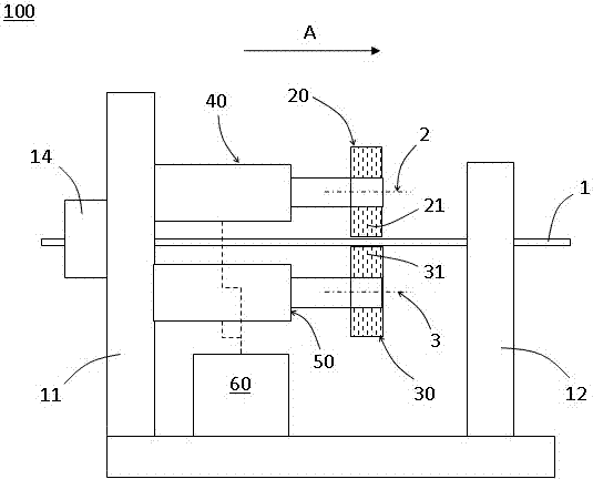
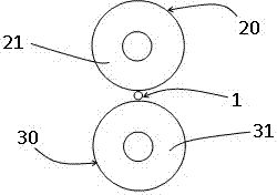
[0020] Please refer to figure 1 and figure 2 , figure 1 It is a schematic diagram of a wire rod mechanical descaling device 100 according to an embodiment of the present invention, figure 2 It is a schematic diagram of the distribution of the first turntable 20 and the second turntable 30 according to an embodiment of the present invention.

[0021] The wire rod mechanical descaling device 100 includes a bracket, a first turntable 20 , a second turntable 30 , a first transmission part 40 , a second transmission part 50 and a driving part 60 .

[0022] The bracket includes a first boss 11 and a second boss 12 , and the first boss 11 and the second boss 12 respectively have wire-passing holes for passing the wire 1 to be derusted along the routing direction A. In one...


PUM


Abstract

The invention provides mechanical derusting equipment for wire rods. The equipment comprises a support, a first turnplate, a second turnplate, a first transmission part, a second transmission part and a drive part. A first boss and a second boss of the support are provided with wire rod penetrating holes allowing a to-be-derusted wire rod to penetrate through in a wire rod arranging direction correspondingly. The first turnplate and the second turnpalte are provided with a first friction part rotating along the first axis and a second friction part rotating along the second axis correspondingly. The second turnplate and the first turnplate are symmetric with respect to the to-be-derusted wire rod penetrating through the wire rod penetrating holes. The to-be-derusted wire rod is located between the first friction part and the second friction part and tightly abuts against both the first friction part and the second friction part. The drive part enables the first turnplate to rotate through the first transmission part, so that the first friction part is driven to rub the to-be-derusted wire rod; and the drive part also enables the second turnplate to rotate through the second transmission part, so that the second friction part is driven to rub the to-be-derusted wire rod. By adoption of the mechanical derusting equipment, the wire rod can be automatically and mechanically derusted, and the working efficiency is improved on the premise that the derusting effect is guaranteed.

Description

technical field [0001] The invention relates to the field of mechanical rust removal, in particular to a wire rod mechanical rust removal device. Background technique [0002] For the rust removal process in the production of steel wire for metal products, most enterprises still stay in the pickling treatment stage. Pickling is a method of chemically removing iron oxide scale on the metal surface. In the pickling of some metals (such as stainless steel), mixed acid pickling (HF+HNO3) is widely used. In the process of mixed acid pickling, a large amount of NOx waste gas will be generated, which will seriously pollute the environment if it is not properly treated and purified. Under the severe situation of "smog", river pollution, and land pollution in various places and the pressure of public opinion on environmental protection, the country's determination to force pollution control is getting stronger and stronger. For enterprises that still adopt the pickling process to r...

Claims


Application Information

Patent Timeline
Patent Type & Authority Applications(China)
IPC IPC(8): B24B27/033B24B41/00B24B41/02
CPCB24B27/033B24B41/005B24B41/02
Inventor 葛云杰
Owner 葛云杰
Why Eureka
Try Eureka