Wall-mounted new energy vehicle charging device

A new energy vehicle and charging device technology, applied in electric vehicle charging technology, charging stations, coupling devices, etc., can solve the problems of large space occupation, poor safety, single function, etc. The effect of solidity and improving work efficiency

Inactive Publication Date: 2017-08-29
苏州玛斯堡威电子科技有限公司
View PDF0 Cites 14 Cited by
  • Summary
  • Abstract
  • Description
  • Claims
  • Application Information

AI Technical Summary

Problems solved by technology

With the continuous development of new energy vehicles, the demand for charging new energy vehicles continues to increase, but the existing charging piles on the market usually have a series of problems during use: single function, poor safety, high price, large footprint and Requires specialized personnel to operate
With the rapid development of electric vehicles and the popularization of civilian use, the existing charging piles cannot meet the actual requirements of various public places and communities. These problems will limit the rapid development of electric vehicles. If there is a charging pile that can meet With the above requirements, and large-scale installation in public places and communities, the penetration rate of electric vehicles will be higher. Therefore, there is an urgent need for a new technical solution to solve the above technical problems.

Method used


Image

  • Wall-mounted new energy vehicle charging device
  • Wall-mounted new energy vehicle charging device
  • Wall-mounted new energy vehicle charging device

Examples


Embodiment Construction

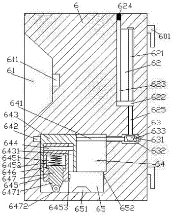
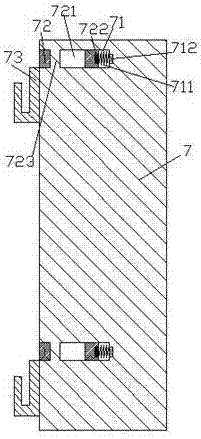
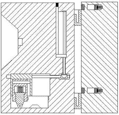
[0026] Such as Figure 1-Figure 8 As shown, a wall-mounted new energy vehicle charging device of the present invention includes a charging box body 6 and a hanger body 7. The charging box body 6 is provided with a first sliding cavity 64, and inside the first sliding cavity 64 The bottom wall is provided with a guide sliding groove 65, and the first sliding cavity 64 is provided with a first screw 641 extending left and right, the left end of the first screw 641 is connected with the first motor 642, and the first screw 641 The upper thread is mated with a first sliding block 643, the first sliding block 643 is provided with a first sliding groove 6431, and the first sliding groove 6431 is provided with a guide sliding rod 644 extending left and right, and the guide sliding The rod 644 is slidably connected with a second sliding block 645, and the bottom of the second sliding block 645 extends into the guide sliding groove 65 and is slidably connected. The second sliding block...


PUM


Abstract

The invention discloses a wall-mounted new energy vehicle charging device. The device comprises a charging box and a hanging frame, a first sliding cavity is formed in the charging box, a guide sliding groove is formed in the inner bottom wall of the first sliding cavity, a first screw extending left and right is arranged in the first sliding cavity, and the left end of the first screw is connected with a first motor; the first screw is matched and connected with a first sliding block through threads, and a first sliding groove is formed in the first sliding block; a guide sliding rod which extends left and right is arranged in the first sliding groove, and a second sliding block is matched and connected with the guide sliding rod in a sliding mode; the bottom of the second sliding block extends into the guide sliding groove and is matched and connected with the guide sliding groove in a sliding mode; a second sliding cavity is formed in the second sliding block, a third sliding block is arranged in the second sliding cavity, and a first spring is arranged at the bottom of the third sliding block; a pushing sliding block penetrating through the bottom end surface of the second sliding block is arranged at the bottom of the third sliding block, a connecting part is arranged at the bottom of the pushing sliding block, and a rolling wheel is arranged at the bottom of the connecting part. The device is simple in structure and convenient to operate, power supply inserting connection can be automatically carried out, installation and dismounting are convenient, and the safety is high.

Description

technical field [0001] The invention relates to the technical field of new energy vehicle charging, in particular to a wall-mounted new energy vehicle charging device. Background technique [0002] Environmental and energy issues are becoming more and more prominent with the development of the automobile industry. Promoting the development of energy-saving and environment-friendly automobiles has become an inevitable trend in the development of the automobile industry. As a safe, less polluting, and low-cost new type of transportation, electric vehicles are supported by the state and policies, and have great potential for development. With the continuous development of new energy vehicles, the demand for charging new energy vehicles continues to increase, but the existing charging piles on the market usually have a series of problems during use: single function, poor safety, high price, large footprint and Specialized personnel are required to operate. With the rapid devel...

Claims


Application Information

Patent Timeline
Patent Type & Authority Applications(China)
IPC IPC(8): B60L11/18H01R13/629H01R13/639
CPCB60L53/16B60L53/31H01R13/62933H01R13/639Y02T10/70Y02T10/7072Y02T90/12Y02T90/14
Inventor 陈柏海
Owner 苏州玛斯堡威电子科技有限公司
Why Eureka
Try Eureka