Automatic shock absorber system for bicycle

A bicycle and shock absorber technology, which is applied to bicycle accessories, shock absorbers, springs/shock absorbers, etc., can solve the problems of uncomfortable riding, hard or soft adjustment of shock absorbers, stability of bicycles with different four-wheeled vehicles, etc. problems, to achieve the effect of improving pedaling efficiency

Active Publication Date: 2017-08-29
GIANT MFG
View PDF4 Cites 6 Cited by
  • Summary
  • Abstract
  • Description
  • Claims
  • Application Information

AI Technical Summary

Problems solved by technology

[0005] However, the existing technology for adjusting the shock absorber has the problem of actual riding, that is, when the shock signal of the front wheel is generated, the shock absorber connected to this signal must respond in a very short time, so it is constantly Action, fast power consumption
In addition, because the front shock absorber also receives the impact at the same time when the front wheel impacts, if the road has a large drop, the adjustment of the shock absorber will be too hard or too soft, making the ride uncomfortable
[0006] In addition, because the front wheel of the bicycle has a steering function, and the bicycle is also different from the stability of the four-wheeled car when riding in the mountain.
However, there is no consistent rule between the actual riding of the bicycle in the mountains and the received signal, so it takes time to analyze the received signal, and the control mechanism can hardly Synchronous correspondence
Accordingly, the method of detecting the degree of road bumps through the acceleration of the front wheels to further control the shock absorbers is not good.

Method used


Image

  • Automatic shock absorber system for bicycle
  • Automatic shock absorber system for bicycle
  • Automatic shock absorber system for bicycle

Examples


no. 1 example

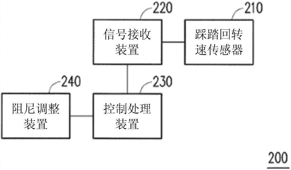
[0110] figure 2 is a block diagram of the bicycle automatic control shock absorber system according to the first embodiment of the present invention. In this embodiment, the bicycle automatic control shock absorber system 200 includes a pedaling speed sensor 210 , a signal receiving device 220 , a control processing device 230 and a damping adjustment device 240 .

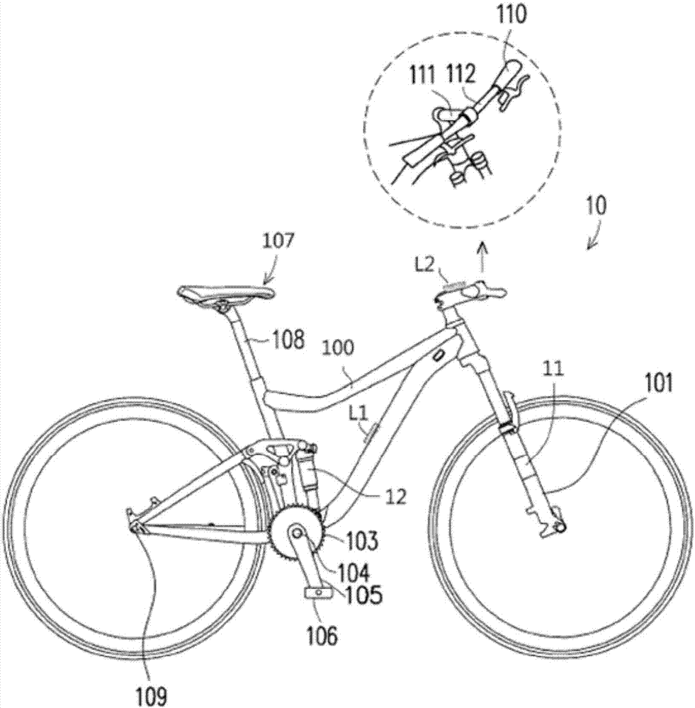
[0111] The pedaling rotation speed sensor 210 is used to detect the pedaling rotation speed of the bicycle 10 and output a pedaling signal. The pedaling speed sensor 210 can be arranged at one of the chainring 103, the crank shaft 104, the crank 105, the pedal 106 and the vehicle frame 100 of the bicycle 10. In addition, the pedaling speed sensor 210 can also be worn on the legs of the rider of the bicycle 10, such as the legs (inner thighs) or shoes.

[0112] The signal receiving device 220 is coupled to the pedaling rotation speed sensor 210 and the control processing device 230 to receive the pedaling signal ...

no. 2 example

[0123] Figure 4A and Figure 4B is a block diagram of the bicycle automatic control shock absorber system according to the second embodiment of the present invention. exist Figure 4A Among them, the bicycle automatic control shock absorber system 400 includes a posture sensor 410 , a signal receiving device 220 , a control processing device 230 and a damping adjustment device 240 . Here, components having the same functions as those in the first embodiment are assigned the same symbols, and related descriptions are omitted.

[0124] The posture sensor 410 is used to detect whether the posture adopted by the rider riding the bicycle 10 is a sitting posture or a standing posture, and outputs a posture signal. The signal receiving device 220 is coupled to the gesture sensor 410 to receive gesture signals. The control processing device 230 is coupled to the signal receiving device 220 , and outputs a level control signal to the damping adjustment device 240 according to the ...

no. 3 example

[0136] Image 6 is a block diagram of the bicycle automatic control shock absorber system according to the third embodiment of the present invention. The bicycle automatic control shock absorber system of this embodiment includes a pedaling speed sensor and a gradient sensor. Please refer to Image 6 The bicycle automatic control shock absorber system 600 includes a pedaling speed sensor 210 , a gradient sensor 610 , a signal receiving device 220 , a control processing device 230 and a damping adjustment device 240 . Here, components having the same functions as those in the first embodiment are assigned the same symbols, and related descriptions are omitted.

[0137] The slope sensor 610 is used to detect the slope of the current location of the bicycle 10 and output a slope signal, and the slope signal is transmitted to the control processing device 230 through the signal receiving device 220 . Here, the control processing device 230 determines the damping curve relations...


PUM


Abstract

An automatic control shock absorber system for a bicycle is provided. A pedaling cadence sensor is configured to detect a pedaling cadence of the bicycle. A control processing device outputs a level control signal to a damping adjustment device according to a pedaling signal such that the damping adjustment device adjusts a level of a damping force according to the level control signal.

Description

[0001] related divisional application [0002] This application is a divisional application of a patent with an application date of November 11, 2014, an application number of 201410630803.5, and an invention titled "Automatic Control Shock Absorber System for Bicycles". technical field [0003] The invention relates to a vehicle suspension system, in particular to an automatic control shock absorber system for a bicycle. Background technique [0004] The general bicycle suspension (suspension) control method mainly uses the impact signal of the front wheel to open or switch the valve of the shock absorber; or uses the impact acceleration of the front wheel to judge the degree of bumpy road surface to control the valve of the shock absorber To adjust its shock-absorbing capacity and response speed. [0005] However, the existing technology for adjusting the shock absorber has the problem of actual riding, that is, when the shock signal of the front wheel is generated, the s...

Claims


Application Information

Patent Timeline
Patent Type & Authority Applications(China)
IPC IPC(8): B62K25/04F16F9/50
CPCB62K25/04F16F9/50
Inventor 陈建宏陈民昌林崇伟
Owner GIANT MFG
Why Eureka
Try Eureka