TLMD vibration isolation system

A vibration damping system and mass block technology, applied in the direction of shock absorbers, shock absorber-spring combinations, shock absorbers, etc., can solve the problem that liquid cannot provide steady-state amplitude and phase difference vibration damping force, etc., to achieve increased The effect of sloshing liquid mass, enhancing vibration damping ability, and reducing vibration

Active Publication Date: 2019-11-26
SHANGHAI NUCLEAR ENG RES & DESIGN INST CO LTD
View PDF7 Cites 2 Cited by
  • Summary
  • Abstract
  • Description
  • Claims
  • Application Information

AI Technical Summary

Problems solved by technology

[0006] The purpose of the present invention is to solve the shortcomings in the prior art, such as: when the excitation frequency is the same as the liquid frequency, the liquid enters the resonance frequency region, at this time due to rotation and eddy, the liquid cannot provide a steady state amplitude and phase differential damping force, and a TLMD damping system proposed

Method used


Image

  • TLMD vibration isolation system
  • TLMD vibration isolation system
  • TLMD vibration isolation system

Examples


Embodiment 1

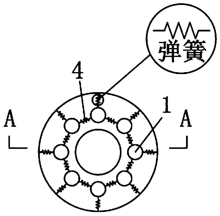
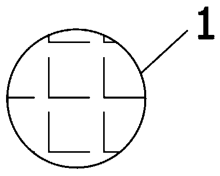
[0032] refer to Figure 1-4 , a TLMD damping system, including TLD and a plurality of TMD, TMD consists of mass 1, first and third spring 7, second spring 4, third spring 7 and liquid 5, TLD also includes liquid 5 and liquid storage Box 6.

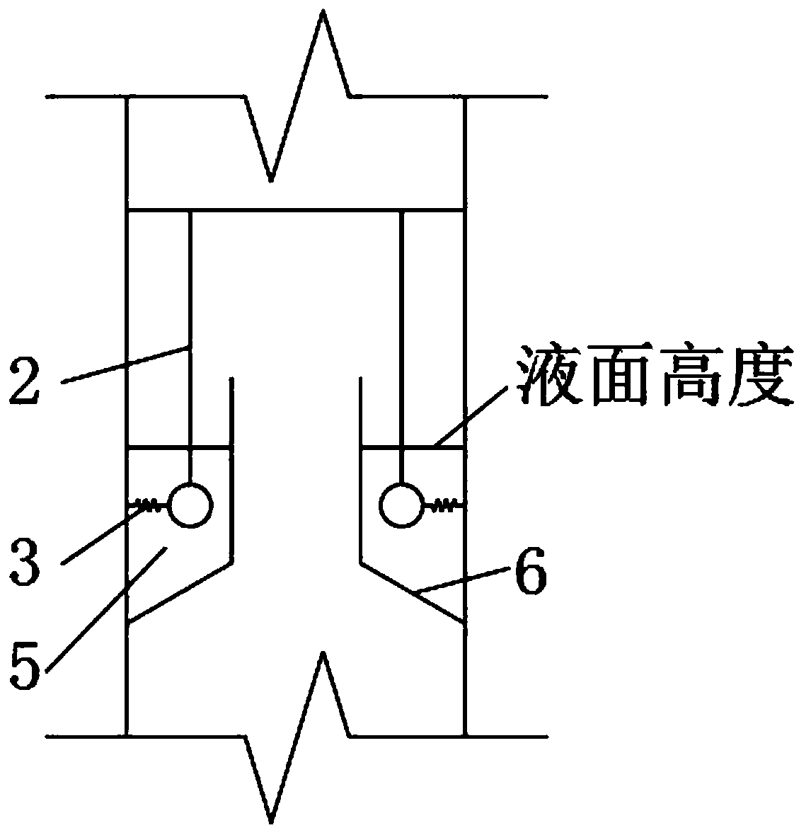
[0033] The present invention arranges a plurality of tuned mass dampers (TMD), and the swing rod 2 is connected with the main structure through a universal hinge to ensure that the mass block 1 can swing along various directions, and the liquid storage tank 6 is welded on the two side walls of the main structure. The mass block 1 , the second spring 4 and the third spring 7 of the TMD are all immersed in the TLD liquid 5 .

[0034] Overall TMD tuning frequency passable Calculate, where L is the length of the pendulum 2, ∑K is the total equivalent stiffness, M is the mass of mass block 1, the number of TMD mass blocks and the frequency value can be selected according to the specific structure and vibration reduction requirements, each ma...

Embodiment 2

[0038] refer to Figure 1-4 , a TLMD damping system, including TLD and a plurality of TMD, TMD consists of mass block 1, first spring 3, second spring 4, third spring 7 and liquid 5, TLD also includes liquid 5 and liquid storage tank 6 .

[0039] The present invention arranges a plurality of tuned mass dampers (TMD), and the swing rod 2 is connected with the main structure through a universal hinge to ensure that the mass block 1 can swing along various directions, and the liquid storage tank 6 is welded on the two side walls of the main structure. The mass block 1 , the first spring 3 , the second spring 4 and the third spring 7 of the TMD are all immersed in the TLD liquid 5 .

[0040] Overall TMD tuning frequency pass-through combine Calculate, where L is the length of the pendulum 2, ∑K is the total equivalent stiffness, M is the mass of mass block 1, the number of TMD mass blocks and the frequency value can be selected according to the specific structure and vibration...


PUM


Abstract

The invention discloses a TLMD vibration isolation system. The system comprises a TLD and multiple TMDs, and each TMD comprises a mass block, a first spring, a second spring, a third spring and liquid; the TLD also comprises liquid and a liquid storage box, and operation steps comprise that before parameters of all parts of the TMDs are selected, the main frequency and external excitation frequency spectrum characteristics of a needed vibration isolation structure are measured, through the vibration isolation need, the modal mass ratio of the TMD and a main structure is determined, and the selection range is 1 to 5%; according to the vibration isolation frequency range determined in S1 and the corresponding mass value, the TMD swing rod length and the spring rigidity are designed, and theTMDs are symmetrically arranged relative to a main structure. The vibration frequency of the mass blocks of the multiple TMDs is adjusted according to the outer motivation, the broadband vibration isolation is achieved, TLD liquid serves as TMD damping liquid, meanwhile, the TLD liquid can vibrate, and through shaking and collision with the wall of the liquid storage box, vibration isolation is achieved.

Description

technical field [0001] The invention relates to the technical field of TLMD vibration damping structures, in particular to a TLMD vibration damping system. Background technique [0002] In order to cope with global climate change and reduce greenhouse gas emissions, my country promulgated and implemented the "Renewable Energy Law of the People's Republic of China" in January 2006 to encourage the development of clean energy and organize the planning of the construction of wind farms across the country. In the past ten years, the wind power base has developed rapidly and has extended from land to sea. Compared with inland wind power, offshore wind power has the advantages of high wind speed, low wind shear, low turbulence, and high output. my country is rich in offshore wind resources and has great potential for wind power development. It is of great practical significance to develop offshore wind resources. [0003] However, the structure of offshore wind power generation ...

Claims


Application Information

Patent Timeline
IPC IPC(8): F16F13/00
CPCF16F13/002
Inventor 褚濛丁振坤豆燚左绍兵
Owner SHANGHAI NUCLEAR ENG RES & DESIGN INST CO LTD
Why Eureka
Try Eureka