Multi-suspension external connection system on electric automobile
An electric vehicle, external connection technology, applied in vehicle components, non-rotational vibration suppression, substructure and other directions, can solve the problems of low assembly difficulty, high assembly efficiency, and high assembly difficulty, and achieves low assembly difficulty and assembly. The effect of high efficiency and reduced installation difficulty
- Summary
- Abstract
- Description
- Claims
- Application Information
AI Technical Summary
Problems solved by technology
Method used
Image
Examples
Embodiment 1
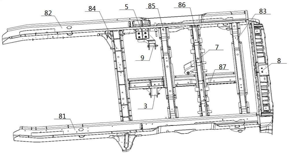
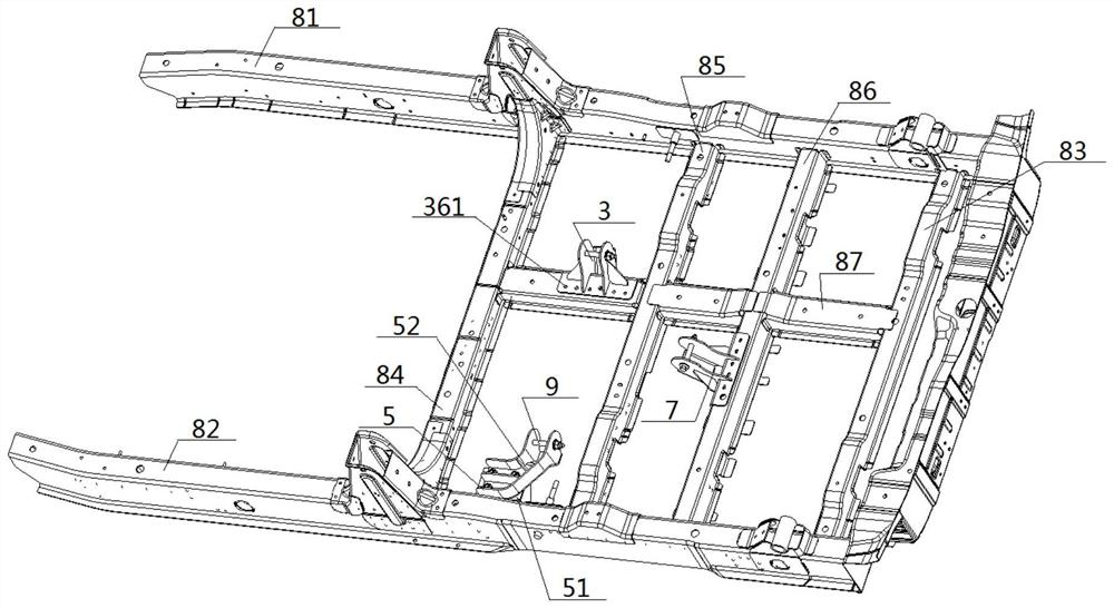
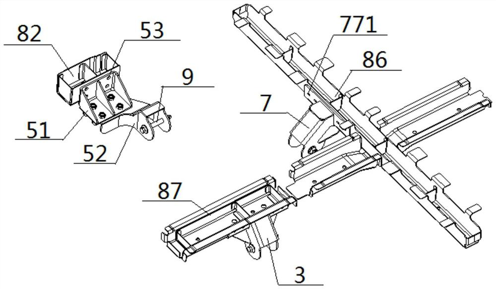
[0073] see figure 1 — Figure 17 , a multi-suspension external connection system on an electric vehicle, comprising a vehicle frame 8 and a suspension connection device connected thereto, the vehicle frame 8 comprising a rear beam 83 and a left longitudinal beam 81 connected to its two ends, Right longitudinal beam 82; the tail end of the left longitudinal beam 81 is connected with the tail end of the right longitudinal beam 82 through the rear cross beam 83, and the middle part of the left longitudinal beam 81 is connected with the middle part of the right longitudinal beam 82 through the No. 1 cross beam 84, The middle part of No. 1 crossbeam 84 is connected with the middle part of back crossbeam 83 by short longitudinal beam 87, and the middle part of short longitudinal beam 87 is vertically connected with the middle part of No. 2 crossbeam 85, No. 3 crossbeam 86 respectively, and the two ends of No. 2 crossbeam 85 are connected with The middle parts of the left longitudin...
Embodiment 2
[0075] Basic content is the same as embodiment 1, the difference is:
[0076] The structure of the left shock absorbing module 20, the right shock absorbing module 40, and the rear shock absorbing module 60 are consistent, and all include a vulcanized sleeve 601, rubber 602, inner shell 603 and outer shell 604; the outer shell of the sleeve 601 Wrapped with rubber 602, the outside of the rubber 602 is wrapped with an inner shell 603, the outside of the inner shell 603 is wrapped with an outer shell 604, and an upper shock-absorbing cavity 605 and a lower shock-absorbing cavity 606 are opened in the rubber 602; The tube passing shafts 9 in the left connection unit 3 , the right connection unit 5 , and the rear connection unit 7 all pass through the corresponding single casing 601 . The central axes of the inner sleeves 601 of the left suspension 2 and the right suspension 4 are parallel to each other, and the central axes of the inner sleeves 601 of the left suspension 2 and th...
Embodiment 3
[0078] Basic content is the same as embodiment 1, the difference is:
[0079] See Figure 17 , this figure is the pointed bolt 10 used when the present invention carries out the bolted connection, and it is also used as the pipe-through shaft 9 simultaneously. The pointed bolt 10 comprises a nut 101, a screw section 102, a threaded section 103, and a bolt head 104 connected in sequence, and the side wall of the threaded section 103 is provided with external threads, and the top of the bolt head 104 is connected to the threaded section. 103, the bottom end of the bolt head 104 extends outwards, and the diameter of the bolt head 104 is tapered from top to bottom.
PUM
 Abstract
Description
Claims
Application Information
 - R&D
- Intellectual Property
- Life Sciences
- Materials
- Tech Scout
- Unparalleled Data Quality
- Higher Quality Content
- 60% Fewer Hallucinations
Browse by: Latest US Patents, China's latest patents, Technical Efficacy Thesaurus, Application Domain, Technology Topic, Popular Technical Reports.
© 2025 PatSnap. All rights reserved.Legal|Privacy policy|Modern Slavery Act Transparency Statement|Sitemap|About US| Contact US: help@patsnap.com


