Beer cap presser capable of effectively improving cap pressing efficiency
A capper and efficient technology, applied in flange-type bottle caps and other directions, can solve the problems of biased caps and straw caps, inaccurate capping positions, affecting beer quality, etc., and achieves high capping efficiency, simple structure, The effect of improving gland efficiency
- Summary
- Abstract
- Description
- Claims
- Application Information
AI Technical Summary
Problems solved by technology
Method used
Image
Examples
Embodiment 1
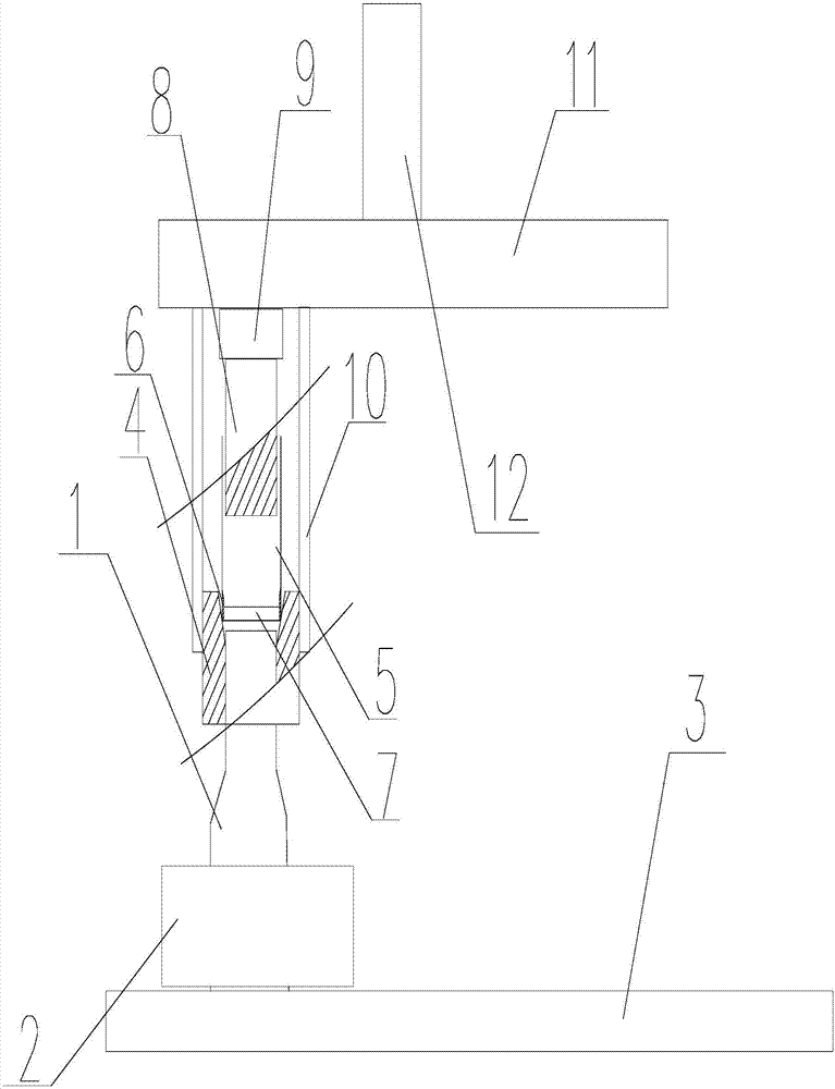
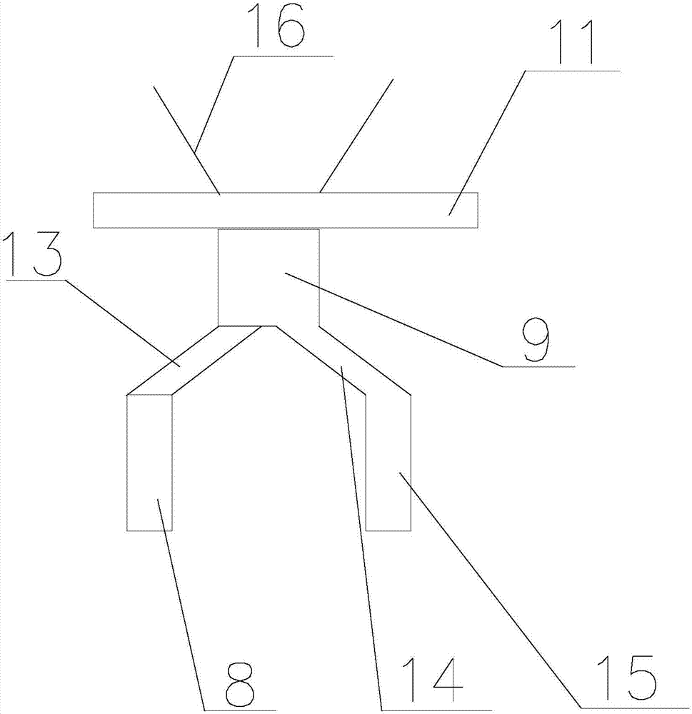
[0025] Such as figure 1 and figure 2 As shown, the present invention effectively improves the beer capper of capping efficiency, comprises beer bottle 1, bottle cap 7, and the top of described beer bottle 1 is connected with the fixed groove 4 that is used for fixing beer bottle 1, and the fixed groove 4 of described fixed groove 4 A channel 5 is connected above, and the side of the upper end of the beer bottle 1 passes through the circular channel in the fixed groove 4, and the upper half of the circular channel is a channel whose diameter gradually increases from bottom to top, and the channel The bottom of the 5 is located in the upper half of the circular passage, and the side of the fixed groove 4 is connected with two connecting rods 10, and a horizontal connecting plate 11 is connected above the connecting rod 10, and the connecting plate 11 is used for connecting The capping device for transporting bottle caps 7 and capping, the capping device is located between two ...
Embodiment 2
[0027] The beer capping device for effectively improving the capping efficiency includes a beer bottle 1 and a bottle cap 7, a fixing groove 4 for fixing the beer bottle 1 is connected above the beer bottle 1, and a fixing groove 4 for fixing the beer bottle 1 is connected above the fixing groove 4. There is a passage 5, the side of the upper end of the beer bottle 1 passes through the circular passage in the fixed groove 4, and the upper half of the circular passage is a passage whose diameter gradually increases from bottom to top, the passage 5 The bottom is located in the upper half of the circular channel, and the sides of the fixing groove 4 are connected with two connecting rods 10, and a horizontal connecting plate 11 is connected above the connecting rods 10, and the connecting plate 11 is connected to a The bottle cap 7 and the capping device for capping, the capping device is located between two connecting plates 11, the capping device includes a rotating device 9, a...
Embodiment 3
[0029] The beer capping device for effectively improving the capping efficiency includes a beer bottle 1 and a bottle cap 7, a fixing groove 4 for fixing the beer bottle 1 is connected above the beer bottle 1, and a fixing groove 4 for fixing the beer bottle 1 is connected above the fixing groove 4. There is a passage 5, the side of the upper end of the beer bottle 1 passes through the circular passage in the fixed groove 4, and the upper half of the circular passage is a passage whose diameter gradually increases from bottom to top, the passage 5 The bottom is located in the upper half of the circular channel, and the sides of the fixing groove 4 are connected with two connecting rods 10, and a horizontal connecting plate 11 is connected above the connecting rods 10, and the connecting plate 11 is connected to a The bottle cap 7 and the capping device for capping, the capping device is located between two connecting plates 11, the capping device includes a rotating device 9, a...
PUM
 Abstract
Description
Claims
Application Information
 - R&D
- Intellectual Property
- Life Sciences
- Materials
- Tech Scout
- Unparalleled Data Quality
- Higher Quality Content
- 60% Fewer Hallucinations
Browse by: Latest US Patents, China's latest patents, Technical Efficacy Thesaurus, Application Domain, Technology Topic, Popular Technical Reports.
© 2025 PatSnap. All rights reserved.Legal|Privacy policy|Modern Slavery Act Transparency Statement|Sitemap|About US| Contact US: help@patsnap.com


