
A Construction Technology for Concreting of Inclined Shafts

A construction technology and concrete technology, applied in shaft equipment, wellbore lining, earthwork drilling, etc., can solve the problems of difficulty in ensuring construction quality, complex construction conditions, large span of inclined wells, etc., to reduce water loss and save construction time. , the effect of saving man-hours

Active Publication Date: 2019-12-17
浙江华东工程咨询有限公司
View PDF5 Cites 0 Cited by
  • Summary
  • Abstract
  • Description
  • Claims
  • Application Information

AI Technical Summary

Problems solved by technology

[0002] Since the late 1980s, my country began to build pumped storage power stations. The water head is generally several hundred meters high, and the length of the diversion inclined shaft is also hundreds of meters. The inclined shaft is a unique building for underground diversion hydropower stations. Concrete lining construction is a project with complicated technology and difficult construction, and the construction conditions are complicated
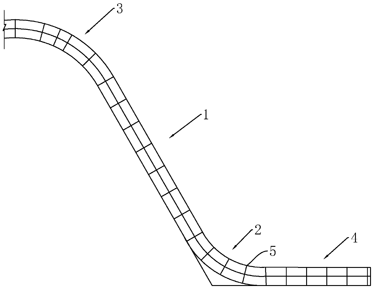
[0004] In the construction of the inclined shaft of the pressure pipeline, due to the large span of the inclined shaft, the soil quality of each rock layer is different, and the concrete pouring range of the inclined shaft includes the upper curved section, the straight section, the lower curved section and the lower flat section, and the construction needs to be targeted , it is difficult to guarantee the construction quality only by slip-form pouring

Method used


Image

  • A Construction Technology for Concreting of Inclined Shafts
  • A Construction Technology for Concreting of Inclined Shafts
  • A Construction Technology for Concreting of Inclined Shafts

Examples


Embodiment Construction

[0044] The present invention will be described in further detail below in conjunction with the accompanying drawings.

[0045] see figure 1 , a construction technique for concrete pouring of inclined shafts, which is applied to the arrangement of inclined shafts of water diversion tunnels in underground works of hydropower stations. The lining concrete pouring construction is carried out on the upper curved section 3, the straight section 1, the lower curved section 2 and the lower flat section 4 of the inclined shaft whose excavation and support construction has been completed.

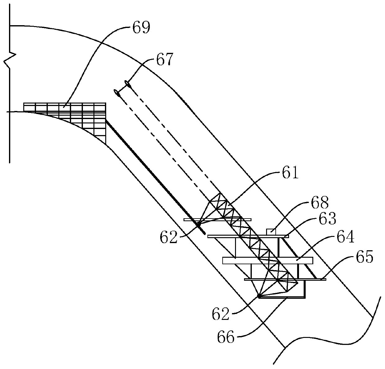
[0046] see figure 2 , in the straight section 1 of the inclined shaft, the concrete is poured through the slip form. The sliding form includes a central beam 61, a sliding form traveling mechanism 62, an operating platform 63, a formwork system 64, a plastering platform 65, a tail platform 66, a wellhead locking beam 67, and a hydraulic climbing system 68. The sliding up of the sliding form utili...


PUM


Abstract

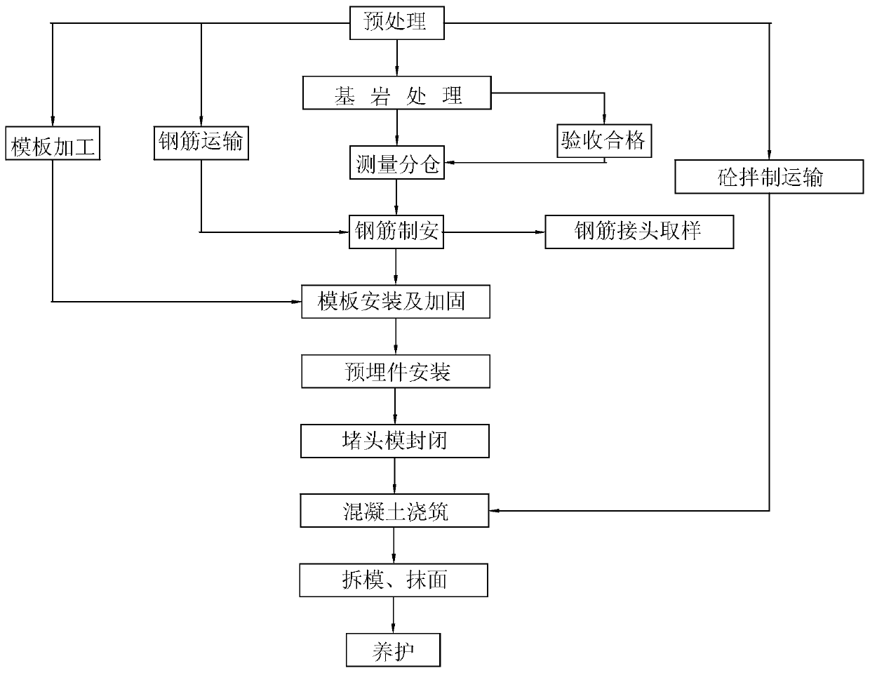
The invention discloses a construction technology for inclined shaft concrete pouring. According to the construction technology for the inclined shaft concrete pouring, the problem that the construction quality is difficult to ensure because the span of an inclined shaft is large, and the soil textures of rock stratums everywhere have differences is solved. According to the technical scheme, the construction technology is characterized in that the range of the inclined shaft concrete pouring comprises an upper bending section, a straight section, a lower bending section and a lower flat section, and the specific construction technology includes the following steps of rock surface cleaning ; paying off and warehouse separating; reinforcing steel bar production and installation; installing of sliding molds on the straight section part of the inclined shaft; examining of the mold surface radian and flatness of a set-shaped steel mold on the upper bending section, the lower bending section and the lower flat section; painting of releasing agents; synchronous conducting of installation and correction; reinforcing by adopting a set-shaped steel arch frame, a steel pipe and a tiepiece; installing of embedded parts; installing of end cap molds; concrete pouring; and demolding and maintenance. The fact that targeted construction is conducted for each section of the inclined shaft is achieved, so that the construction quality is improved.

Description

technical field [0001] The invention relates to building construction, in particular to a construction technique for pouring concrete in inclined shafts. Background technique [0002] Since the late 1980s, my country has begun to build pumped storage power stations. The water head is generally as high as several hundred meters, and the length of the diversion inclined shaft is also hundreds of meters. The inclined shaft is a unique building for underground diversion hydropower stations. Concrete lining construction is a project with complicated technology and difficult construction, and the construction conditions are complicated. [0003] Such as the authorized announcement number is CN1261672C patent discloses a kind of construction method of concrete lining slipform of steep-inclination large-diameter inclined shaft, a hydraulic lifting system is installed on the slip-form form body of steep-inclination large-diameter long inclined shaft concrete lining, and the system con...

Claims


Application Information

Patent Timeline
Patent Type & Authority Patents(China)
IPC IPC(8): E21D11/10E21D11/14E21D11/18E21D11/38E21F16/00
CPCE21D11/10E21D11/107E21D11/14E21D11/18E21D11/38E21F16/00
Inventor 王洪超徐军珲杜鹏唐雷宁昭印
Owner 浙江华东工程咨询有限公司
Learn More