Rocket based combined cycle engine combustion chamber

A combustion chamber and engine technology, which is applied to rocket engine devices, machines/engines, mechanical equipment, etc., can solve problems such as large variation range and complex actuating mechanism, and achieve the effect of improving thrust and specific impulse performance

Active Publication Date: 2017-08-29
NORTHWESTERN POLYTECHNICAL UNIV
View PDF5 Cites 1 Cited by
  • Summary
  • Abstract
  • Description
  • Claims
  • Application Information

AI Technical Summary

Problems solved by technology

However, the range of changes in the above schemes is too l

Method used


Image

  • Rocket based combined cycle engine combustion chamber
  • Rocket based combined cycle engine combustion chamber
  • Rocket based combined cycle engine combustion chamber

Examples


Embodiment Construction

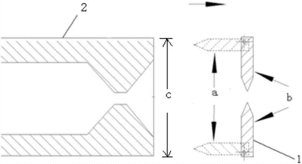
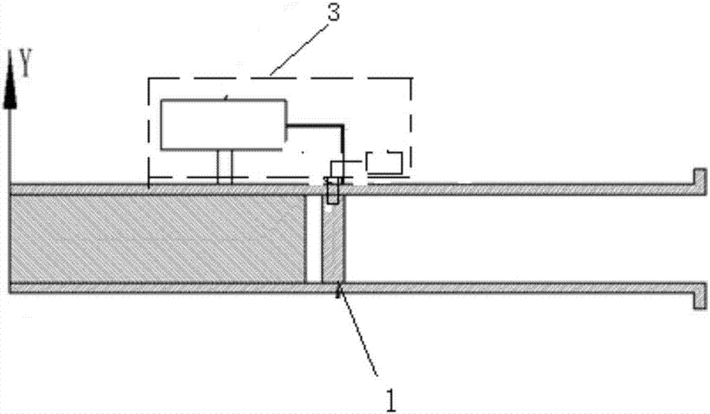
[0010] Rocket-based combined cycle engine combustion chamber of the present invention, such as figure 1 and figure 2 As shown, including the combustion chamber cavity, two fuel support plates 1 are vertically arranged in the combustion chamber cavity, and their heights are consistent with the height of the combustion chamber cavity; the rear ends of the two fuel support plates 1 pass through The rotating shaft is installed in the combustion chamber cavity; when the support plate rocket combustion chamber is working and the high-temperature gas enters the combustion chamber cavity through the exit of the support plate rocket nozzle, the two fuel support plates 1 are consistent with the direction of the combustion chamber cavity , and their front and rear ends are all on the corresponding same cross-section; when the support plate rocket combustion chamber stops working, and when the support plate rocket nozzle outlet no longer ejects high-temperature gas, the two fuel support ...


PUM


Abstract

The invention discloses a rocket based combined cycle engine combustion chamber which comprises a combustion chamber cavity. Two fuel support plates are vertically arranged in the combustion chamber cavity, and the height of the fuel support plates is consistent with that of the combustion chamber cavity. The rear ends of the two fuel support plates are mounted in the combustion chamber cavity through rotary shafts. When the support plate rocket combustion chamber works, the two fuel support plates are consistent with the incoming flow direction, the front ends of the two fuel support plates are on the corresponding same cross section, and the rear ends of the two fuel support plates are on the corresponding same cross section. When the support plate rocket combustion chamber stops working, the two fuel support plates rotate around the rotary shafts in different directions to be perpendicular to the incoming flow direction, and the two fuel support plates are on the same straight line so as to divide the combustion chamber cavity into a first-stage return flow zone in front of the fuel support plates and a second-stage return flow zone behind the fuel support plates. The rocket based combined cycle engine combustion chamber meets air flow matching under different incoming flow conditions.

Description

technical field [0001] The invention belongs to the technical field of rocket-based combined cycle engines, and in particular relates to a combustion chamber of a rocket-based combined cycle engine. Background technique [0002] The Rocket-Based-Combined-Cycle (RBCC) engine has potential advantages such as reusability, low cost, and high reliability, and is considered to be one of the propulsion systems most likely to be used in future space-to-ground transportation systems. one. The RBCC engine integrates ejection mode, sub-combustion mode, super-combustion mode and pure rocket mode. In order to take into account a wide range of work, the way of changing the configuration of the combustion chamber is often used. In super-combustion mode, in order to meet the needs of supersonic combustion, the flow channel of the combustion chamber needs to maintain an expanding structure; while in the injection and sub-combustion modes, the flow channel of the combustion chamber needs to...

Claims


Application Information

Patent Timeline
IPC IPC(8): F02K9/34F02K9/62
CPCF02K9/34F02K9/62
Inventor 魏祥庚李江秦飞张时空石磊何国强潘宏亮
Owner NORTHWESTERN POLYTECHNICAL UNIV
Why Eureka
Try Eureka