

Radar covariance matrix reconstruction beam forming method based on iteration mutual coupling calibration
A technology of covariance matrix and mutual coupling matrix, used in radio wave measurement systems, instruments, etc., can solve problems such as performance degradation, array antenna receiving signal mismatch, observation angle error, etc., to improve real-time performance and reduce computational complexity. , the effect of improving the robustness
Active Publication Date: 2017-08-29
XIDIAN UNIV
View PDF4 Cites 6 Cited by
- Summary
- Abstract
- Description
- Claims
- Application Information
AI Technical Summary
Problems solved by technology
In many practical application fields, the performance of the adaptive beamformer will be affected by various error factors, such as signal observation error, receiving channel error, array element position error, etc. These errors will cause the steering vector mismatch of the array antenna receiving signal , leading to a decrease in the performance of the beamforming algorithm; and when the sample snapshot contains the desired signal, the mismatch of the steering vector has a particularly significant impact on the performance of the adaptive beamformer
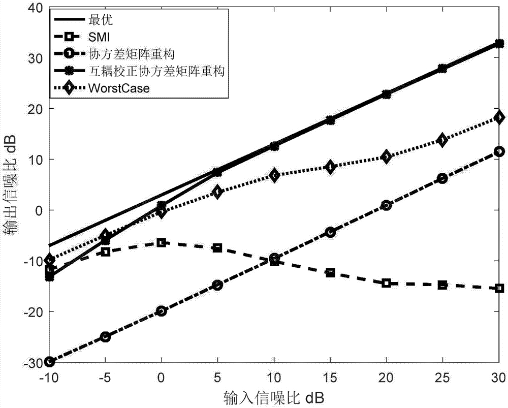
In 1991, Benjamin Friedlander and W Anthony J. Weiss proposed a DOA estimation method when there is mutual coupling between array elements, which can accurately estimate the DOA of the signal's direction of arrival and the mutual coupling between uniform circular arrays, but The DOA estimation method in the presence of mutual coupling between array elements has not been applied in the field of adaptive beamforming technology; in 2012, Gu proposed a beamforming method based on the reconstruction of the interference plus noise covariance matrix. The constructed covariance matrix replaces the expected polluted sampling covariance matrix to calculate the adaptive weight vector. Although it has better performance when the expected signal power is stronger, this method has the following two problems in practical applications: first , this method requires that the array configuration is known precisely, and the only allowable error is the observation angle error, and the performance is greatly degraded when considering the mutual coupling effect; second, the method is computationally complex when reconstructing the interference-plus-noise covariance matrix The degree is very large, which restricts the real-time performance of the algorithm
Method used
View moreImage
Smart ImageViewing Examples

Examples
Embodiment Construction
Login to View More PUM
 Abstract
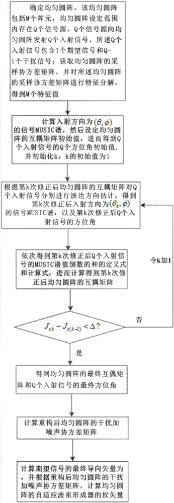
The present invention discloses a radar covariance matrix reconstruction beam forming method based on iteration mutual coupling calibration. The method thinking comprises: an uniform circular array is determined, the uniform circular array comprises M array elements, there are Q signal sources in the setting range of the uniform circular array, the Q signal sources emit Q incident signals to the uniform circular array, and the Q incident signals comprise one desired signal and Q-1 interference signals; the sampling covariance matrix R of the uniform circular array is obtained, the characteristic decomposition is performed, and M characteristic values are obtained; a signal MUSIC spectrum having an incident direction of ([Theta], [Phi]) is calculated, the mutual coupling matrix initial value of the uniform circular array is set to obtain Q azimuth initial values of the Q incident signals, and a final mutual coupling matrix of the uniform circular array (img file='DDA0001335531130000011.TIF' wi='43' he='57' / ) and the final azimuths of the Q incident signals (img file='DDA0001335531130000012.TIF' wi='67' he='58' / ) are obtained; and the interference-plus-noise covariance matrix of the uniform circular array after the reconstruction (img file='DDA0001335531130000013.TIF' wi='116' he='73' / ) is calculated to obtain the weight vector of the adaptive beam former of the uniform circular array so as to complete the reconstruction of the interference-plus-noise covariance matrix of the uniform circular array based on the iteration mutual coupling calibration.
Description
Radar Covariance Matrix Reconstruction Beamforming Method Based on Iterative Mutual Coupling Correction technical field The invention belongs to the technical field of conformal array antenna beamforming, and particularly relates to a radar covariance matrix reconstruction beamforming method based on iterative mutual coupling correction, which is suitable for solving the problem that the adaptive beamformer is robust due to the strong expected signal power in sampling samples The problem of performance degradation, and the performance degradation of the beamformer when considering the mutual coupling effect, and the robust performance of the beamformer is improved while considering the mutual coupling effect between array elements. Background technique Conformal arrays have been widely used due to their advantages of electromagnetic concealment, large scanning angle, small load weight, and no interference with the aerodynamic flow field of flying objects; however, conformal...
Claims
Login to View More Application Information
Patent Timeline
 Patent Type & AuthorityApplications(China)
IPC IPC(8): G01S7/02
CPCG01S7/02
Inventor王彤解彩莲胡艳艳李博文
OwnerXIDIAN UNIV