Electronic type phase conversion switch

An electronic, phase-inverting technology, which is applied in the direction of reducing the asymmetry of electrical components, circuit devices, and multi-phase networks, can solve the problems of long commutation switching time, unbalanced three-phase load, and asymmetrical three-phase load. Achieve the effects of simplifying electrical control, improving reliability and reducing switching time

Pending Publication Date: 2017-08-29
NANJING XINLIAN ENERGY TECH
View PDF2 Cites 4 Cited by
  • Summary
  • Abstract
  • Description
  • Claims
  • Application Information

AI Technical Summary

Problems solved by technology

[0002] The main reason for the unbalanced three-phase load in the low-voltage distribution network is the asymmetry of the three-phase load. Due to the uneven distribution of single-phase users, uncontrollable capacity increase, and the access of high-power single-phase loads, the power consumption behavior is affected by seasonality. Randomness, and lack of attention to the management of three-phase load balance make the problem of three-phase load imbalance more serious
[0003] The phase-reversing switch is a common device to deal with the three-phase unbalance problem on the power grid at present; when the current of a certain phase of the live wire is too large, the phase sequence of the live wire connected to the user side can be switched through the phase-reversing switch, so that the phase with a heavier connection load can be transferred To the phase with light load, the utilization rate and availability of grid power can be improved by balancing the current of each phase; most of the phase-rotation switches currently used are based on mechanical, and the rotation of the movable contact around the center of the turntable is connected to realize the rotation. The biggest advantage of this switch is that it is naturally mutually exclusive, that is, it will not be short-circuited between phases; but the mechanical switch has the following disadvantages: 1. Electrical control is more troublesome, usually realized by a motor, and the motor is usually not reliable. High, and the rotation angle is difficult to control; 2. During mechanical switching, when the current is large, there will be arcing phenomenon, which will burn out the contacts in severe cases; 3. The commutation switching time is long, usually more than 200ms, causing user side device restart

Method used


Image

  • Electronic type phase conversion switch
  • Electronic type phase conversion switch
  • Electronic type phase conversion switch

Examples


Embodiment 1

[0044] Grid voltage 220V, frequency 50HZ, clockwise phase rotation:

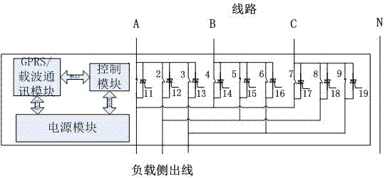
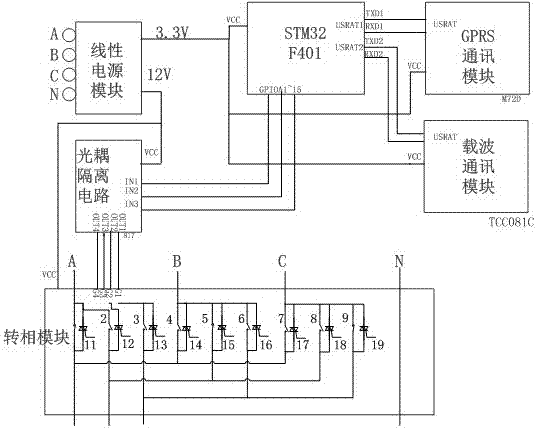
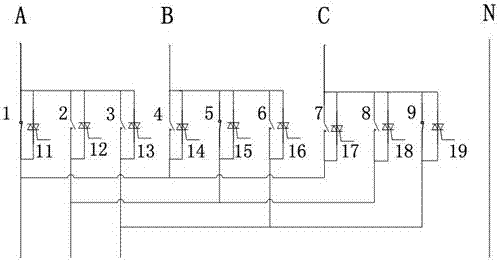
[0045] 1) In the initial state, A magnetic latching relay 1, E magnetic latching relay 5, and I magnetic latching relay 9 are closed, and the remaining magnetic latching relays and all thyristors are all disconnected. At this time, the circuit is controlled by A magnetic latching relay 1, E magnetic latching relay Holding relay 5 and I magnetic holding relay 9 supply power, and the phase sequence of the outgoing line on the load side is A, B, C;

[0046] 2) After receiving the clockwise phase rotation command:

[0047] 2.1 Turn on A anti-parallel thyristor 11, E anti-parallel thyristor 15, I anti-parallel thyristor 19, and wait for 20ms;

[0048] 2.2 A magnetic latching relay 1, E magnetic latching relay 5, and I magnetic latching relay 9 are disconnected. Wait for 100ms to ensure that the magnetic latching relay is completely disconnected. At this time, the line is composed of A anti-parallel thyristor 11,...

Embodiment 2

[0055] Grid voltage 220V, frequency 50HZ, counterclockwise phase rotation:

[0056] 1) In the initial state, A magnetic latching relay 1, E magnetic latching relay 5, and I magnetic latching relay 9 are closed, and the remaining magnetic latching relays and all thyristors are all disconnected. At this time, the circuit is controlled by A magnetic latching relay 1, E magnetic latching relay Holding relay 5 and I magnetic holding relay 9 supply power, and the phase sequence of the outgoing line on the load side is A, B, C;

[0057] 2) After receiving the counterclockwise phase rotation command:

[0058] 2.1 Turn on A anti-parallel thyristor 11, E anti-parallel thyristor 15, I anti-parallel thyristor 19, and wait for 20ms;

[0059] 2.2 A magnetic latching relay 1, E magnetic latching relay 5, and I magnetic latching relay 9 are disconnected. Wait for 100ms to ensure that the magnetic latching relay is completely disconnected. At this time, the line is composed of A anti-parallel...


PUM


Abstract

The present invention provides an electronic type phase conversion switch. The structure of the switch comprises a phase conversion module; and the phase conversion module comprises an A magnetic latching relay, a B magnetic latching relay, a C magnetic latching relay, a D magnetic latching relay, an E magnetic latching relay, an F magnetic latching relay, a G magnetic latching relay, an H magnetic latching relay, an I magnetic latching relay, an A anti-parallel thyristor, a B anti-parallel thyristor, a C anti-parallel thyristor, a D anti-parallel thyristor, an E anti-parallel thyristor, an F anti-parallel thyristor, a G anti-parallel thyristor, an H anti-parallel thyristor and an I anti-parallel thyristor. The electronic type phase conversion switch is employed to reduce the switching time of a mechanical type phase inversion switch and control the phase inversion time in 11ms so as to realize phase conversion with continuous electricity at a user side, improve the reliability and simplify the electrical control.

Description

technical field [0001] The invention relates to an electronic phase-reversing switch, which belongs to the technical field of electric energy quality control in electric power systems. Background technique [0002] The main reason for the unbalanced three-phase load in the low-voltage distribution network is the asymmetry of the three-phase load. Due to the uneven distribution of single-phase users, uncontrollable capacity increase, and the access of high-power single-phase loads, the power consumption behavior is affected by seasonality. Randomness, and lack of attention to the management of three-phase load balance make the problem of three-phase load imbalance more serious. [0003] The phase-reversing switch is a common device to deal with the three-phase unbalance problem on the power grid at present; when the current of a certain phase of the live wire is too large, the phase sequence of the live wire connected to the user side can be switched through the phase-reversi...

Claims


Application Information

Patent Timeline
Patent Type & Authority Applications(China)
IPC IPC(8): H02J3/26H02J13/00
CPCH02J13/0017H02J3/26Y02E40/50
Inventor 王爱民
Owner NANJING XINLIAN ENERGY TECH
Why Eureka
Try Eureka