Slope compensation circuit
A slope compensation and slope voltage technology, applied in electrical components, adjusting electrical variables, instruments, etc., can solve problems such as difficulty and increase circuit area, and achieve the effect of saving area
- Summary
- Abstract
- Description
- Claims
- Application Information
AI Technical Summary
Problems solved by technology
Method used
Image

Examples
Embodiment Construction
[0015] The present invention will be described in detail below in conjunction with the accompanying drawings.
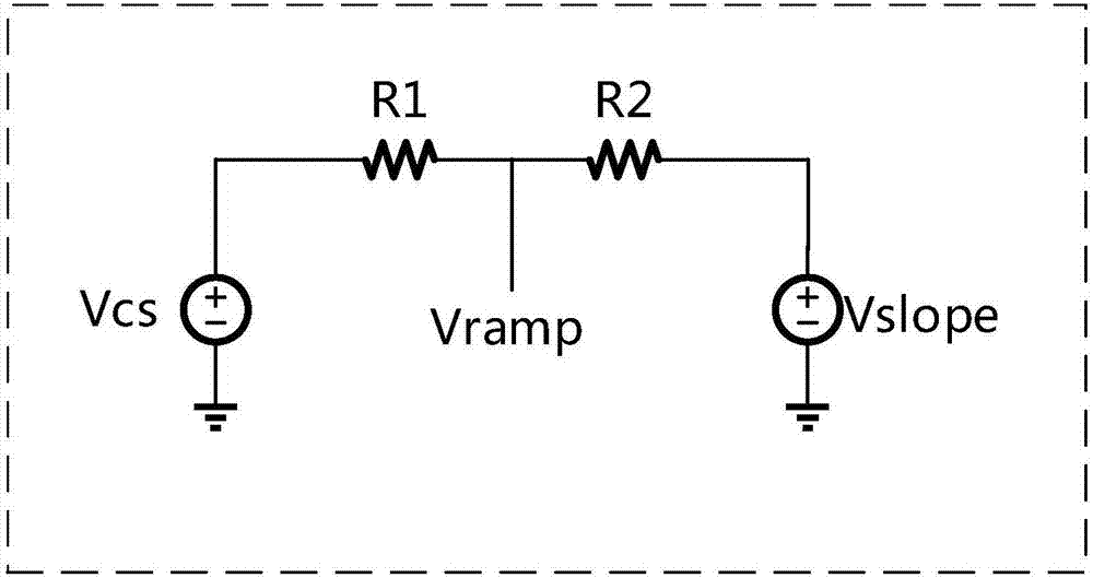
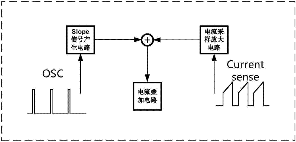
[0016] Figure 4 It is a functional block diagram of the slope compensation circuit of the present invention superimposing the slope voltage at the current sampling signal. As shown in the figure, the current sampling signal entering from the CS port will be superimposed with a value of (I slope *R1) After the slope compensation signal, it is compared with the error amplifier signal Ve to generate a PWM square wave control signal, and finally a PWM signal is generated after passing through an SR latch whose S terminal is connected to the clock signal.
[0017] Figure 5 It is a slope voltage generating circuit, a bias current mirror I1 charges the capacitor C2, and the slope remains basically unchanged due to the small current and large capacitance. When the period begins, the clock signal CLK outputs a narrow square wave, which makes the NMOS transistor MN3 open,...
PUM
 Abstract
Description
Claims
Application Information
 - R&D
- Intellectual Property
- Life Sciences
- Materials
- Tech Scout
- Unparalleled Data Quality
- Higher Quality Content
- 60% Fewer Hallucinations
Browse by: Latest US Patents, China's latest patents, Technical Efficacy Thesaurus, Application Domain, Technology Topic, Popular Technical Reports.
© 2025 PatSnap. All rights reserved.Legal|Privacy policy|Modern Slavery Act Transparency Statement|Sitemap|About US| Contact US: help@patsnap.com