
Rotor excitation method and device of synchronous motor

A rotor excitation and synchronous motor technology, applied in circuit devices, control generators, winding excitation motor control, etc., can solve the problems of low reliability, sensitive transmission distance, few inductive transmission, etc., and achieve power transmission efficiency High, structurally stable and reliable effect

Inactive Publication Date: 2017-08-29
TONGJI UNIV
View PDF5 Cites 17 Cited by
  • Summary
  • Abstract
  • Description
  • Claims
  • Application Information

AI Technical Summary

Problems solved by technology

Brushed electric excitation transmits the electric energy of the stator end to the rotor end through the brush, and the structure is simple, but due to the mechanical contact between the brush and the slip ring between the stator and the rotor, the two often cause heat and damage due to poor contact, etc., reliability Not high; the current brushless excitation generator is often composed of an exciter and a motor. The excitation power of the generator is generated by the exciter and rectified. It is often used in generators and rarely used in motors.
There is also an alternating magnetic field excited on the primary side (stator side), and the alternating magnetic field transmits the excitation current through the coil turn chain on the secondary side (rotor side) through the principle of electromagnetic induction, but the inductive transmission is very sensitive to the transmission distance, and the transmission efficiency is also low. Fluctuates greatly with load

Method used


Image

  • Rotor excitation method and device of synchronous motor
  • Rotor excitation method and device of synchronous motor
  • Rotor excitation method and device of synchronous motor

Examples


Embodiment Construction

[0024] The present invention will be described in detail below in conjunction with the accompanying drawings and specific embodiments. This embodiment is carried out on the premise of the technical solution of the present invention, and detailed implementation and specific operation process are given, but the protection scope of the present invention is not limited to the following embodiments.

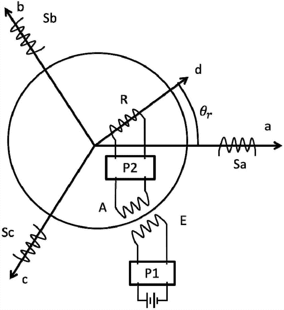
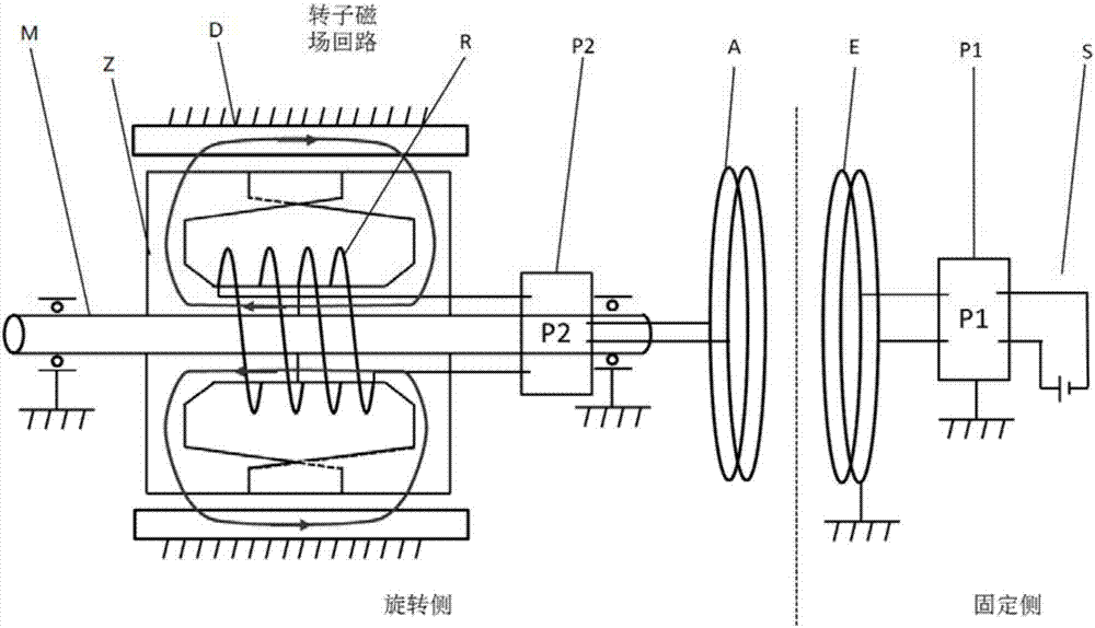
[0025] The invention provides a rotor excitation method of a synchronous motor. The method adopts a resonant wireless power transmission method to transmit the electric energy of a DC or AC power supply to the excitation winding of the rotor to realize wireless excitation and realize electric energy transmission between the fixed side and the rotating part of the motor, and There is no mechanical contact. The rotor excitation can adopt separate electric excitation according to the actual needs, that is, the rotor magnetic field is all established by the excitation current; it can also...


PUM


Abstract

The invention relates to a rotor excitation method and device of a synchronous motor. According to the method, electric energy of a DC / AC power supply is transmitted to a rotor excitation winding in a non-contact mode by employing a resonant wireless electric energy transmission mode, so that rotor electrical excitation or hybrid electrical excitation is achieved. The device comprises an emission end and a receiving end, wherein the emission end is fixedly combined with an engine base, the receiving end synchronously rotates with a rotor and is connected with the rotor excitation winding, the emission end comprises a resonant excitation circuit, an emission end compensation circuit and an emission coil which are connected, the receiving end comprises a receiving coil, a receiving end compensation circuit and rectification conversion circuit which are connected, the rectification conversion circuit is connected with the rotor excitation winding, and the resonant excitation circuit comprises a power input interface and is used for inputting the electric energy from the power supply and continuing to simulate the emission coil and the emission end compensation circuit to work in a resonant state. Compared with the prior art, the device has the advantage of a reliable structure, wireless excitation can be achieved, and an excitation current can be adjusted to satisfy the running demand of the motor under various working conditions.

Description

technical field [0001] The invention belongs to the technical field of motors and controls, and in particular relates to a method and device for exciting a rotor of a synchronous motor. Background technique [0002] At present, there are mainly two methods for external excitation of the motor rotor magnetic field, including inductive excitation and electric excitation. [0003] The inductive excitation method transmits electric energy based on the principle of electromagnetic induction. It is represented by the application of asynchronous motors. By injecting a specific form of current into the stator coil, a magnetic field is formed and the excitation current at the rotor end is induced by the stator-rotor speed difference. The inductive excitation method The obvious disadvantage is that the efficiency is low, which leads to the relatively low efficiency of the motor using the induction excitation method. [0004] The electric excitation method directly injects the excitat...

Claims


Application Information

Patent Timeline
IPC IPC(8): H02P6/32H02P9/08H02J50/12H01F38/14
CPCH02P6/32H01F38/14H02J50/12H02P9/08
Inventor 钟再敏秦一进江尚李俊杰
Owner TONGJI UNIV
Learn More