A low power ideal diode control circuit

A circuit and gate technology, applied in the field of circuit design, can solve problems such as unavailability

Active Publication Date: 2017-08-29
TEXAS INSTR INC
View PDF5 Cites 1 Cited by
  • Summary
  • Abstract
  • Description
  • Claims
  • Application Information

AI Technical Summary

Problems solved by technology

Schottky diodes can reduce this voltage drop, but Schottk

Method used


Image

  • A low power ideal diode control circuit
  • A low power ideal diode control circuit
  • A low power ideal diode control circuit

Examples


Embodiment Construction

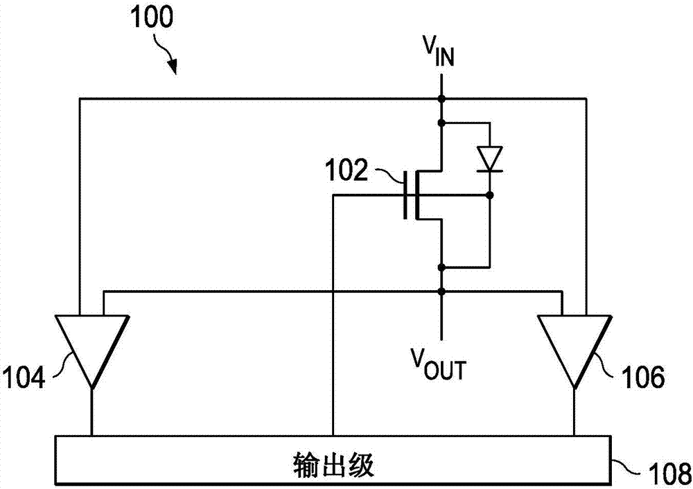
[0013] The main purpose of a diode is to allow current flow in one direction. Ideally, this means zero forward bias voltage drop, zero reverse current and zero equivalent series resistance when forward biased. The closest approximation to these ideal characteristics can be achieved by using a single transistor as a switch and controlling the gate voltage according to the voltage across the transistor. Several timing issues are also important in the optimal operation of ideal diodes. For example, if a diode is conducting in the forward state and is immediately switched to the reverse state, the diode will conduct in the reverse direction for a short time due to the forward voltage bleed off. During this small recovery time, called the reverse recovery time, the current through the diode will be quite large in the reverse direction. After the carriers have leveled and the diode operates in the reverse state as a normally blocking device, the current should drop to the leakage ...


PUM


Abstract

The invention discloses a low power ideal diode control circuit. In described examples of a circuit (100) that operates as a low-power ideal diode, the circuit (100) includes a p-channel transistor (102) connected to receive an input voltage (VIN) on a first terminal and to provide an output voltage (VOUT) on a second terminal, a first amplifier (106) connected to receive the input voltage and the output voltage and to provide a first signal that dynamically biases a gate of the p-channel transistor (102) as a function of the voltage across the p-channel transistor, and a second amplifier (104) connected to receive the input voltage and the output voltage and to provide a second signal that operates to turn off the gate of the p-channel transistor (102) responsive to the input voltage (VIN) being less than the output voltage (VOUT).

Description

technical field [0001] The present disclosure relates generally to the field of circuit design, and more particularly to circuits, chips and methods of controlling transistors to provide the functionality of an ideal diode with both fast forward recovery and fast reverse recovery. Background technique [0002] In low power applications where diodes are required, the forward voltage drop of the diodes can create supply headroom issues or excessive power dissipation. Schottky diodes can reduce this voltage drop, but Schottky diodes are not available in many semiconductor processes. To avoid these problems, a single transistor can be used instead of a diode, with the gate voltage of the transistor controlled to operate as an ideal diode. For very low power applications, so-called "ideal diode" circuits have fast forward drop recovery and fast reverse recovery with low voltage headroom. Contents of the invention [0003] In the depicted example, an ideal diode circuit may in...

Claims


Application Information

Patent Timeline
IPC IPC(8): H02M7/217
CPCG05F1/575
Inventor T·B·莫金H·P·弗汉尼-扎德
Owner TEXAS INSTR INC
Why Eureka
Try Eureka