Mould fixing structure for backward extrusion and backward extrusion method

A technology of reverse extrusion and fixed structure, applied in the direction of metal extrusion dies, etc., can solve the problems of increased production cost, long non-extrusion time, complicated extrusion process, etc., to improve production efficiency, reduce production cost, shorten The effect of unsqueezed time

Inactive Publication Date: 2017-09-01
CHINA NAT HEAVY MACHINERY RES INSTCO
View PDF5 Cites 3 Cited by
  • Summary
  • Abstract
  • Description
  • Claims
  • Application Information

AI Technical Summary

Problems solved by technology

This makes the extrusion process complicated, resulting in a decrease in work efficiency and greatly increasing production costs
[0003] The reverse extrusion method of the movable mold, in each extrusion process, the mold is sent in and taken out, and the residual material needs to be separated after taking out, resulting in a long non-extrusion time, and it is necessary to configure the mold separation, feeding and Take out and other complex mechanized devices

Method used


Image

  • Mould fixing structure for backward extrusion and backward extrusion method
  • Mould fixing structure for backward extrusion and backward extrusion method

Examples


Embodiment 1

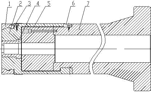
[0021] This embodiment provides a mold fixing structure for reverse extrusion, comprising a mold 4, a reverse extrusion die shaft 7, the reverse extrusion die shaft 7 is installed on a movable mold base, and the mold 4 is covered with a mold Cover 2, the mold cover 2 is connected with the reverse extrusion die shaft 7, a mold support 5 is provided between the mold 4 and the reverse extrusion die shaft 7, and the mold support 5 is arranged in the die cover 2 and It is fixedly connected with the reverse extrusion die shaft 7, and the mold 4, the die support 5 and the reverse extrusion die shaft 7 are all coaxial.

[0022] Using process: Fix the mold 4 on the reverse extrusion mold shaft 7 through the mold support 5 and the mold sleeve 2, and then send the ingot and the mold 4 to the extrusion center by the mobile mold base, and start extrusion. Only need to take and deliver the ingot until all the ingots are extruded and taken out of the mold 4 .

[0023] Fixing the mold 4 simp...

Embodiment 2

[0025] On the basis of embodiment 1, this embodiment provides a kind of figure 1 In the shown die fixing structure for reverse extrusion, the mold sleeve 2 is provided with an expansion ring 1 at one end, and the other end is connected with the reverse extrusion die shaft 7 .

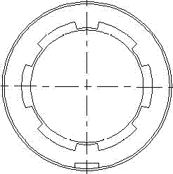
[0026] During the extrusion process, the expansion ring 1 protruding into the extrusion cylinder is expanded by the extrusion force, and the contact with the inner wall of the extrusion cylinder prevents the aluminum billet from entering the reverse extrusion die shaft 7 and extruding The gap between the cylinders is convenient for later cleaning. The structure of the expansion ring 1 is as figure 2 shown.

[0027] In this embodiment, the mold support 5 is a hollow structure with assembly holes arranged in the circumferential direction, the inner diameter of the mold support 5 is equal to the inner diameter of the mold 4 , and the outer diameter is larger than the outer diameter of the mold 4 . The ...

Embodiment 3

[0031] On the basis of Embodiment 1, this embodiment provides a mold fixing structure for reverse extrusion, and a radial gap is reserved between the mold support 5 and the mold sleeve 2 .

[0032] There is a gap reserved in the radial direction between the mold support 5 and the mold sleeve 2, which can ensure that the expansion ring 1, the mold sleeve 2 and the mold 4 can be flexibly aligned when they extend into the extrusion cylinder, and ensure that the extrusion rod, extrusion cylinder, mold 4 and Concentricity of reverse extrusion die axis 7.

[0033] Such as figure 1 As shown, the inner diameter of the counter-extrusion die shaft 7 is larger than the inner diameter of the die support 5 .


PUM


Abstract

The invention provides a mold fixing structure for reverse extrusion and a reverse extrusion method, comprising a mold, a reverse extrusion die shaft, the reverse extrusion die shaft is installed on a movable mold frame, and the outer mold is provided with A die set, the die set is connected to the reverse extrusion die shaft, a die support is provided between the die and the reverse extrusion die shaft, the die support is arranged in the die sleeve and connected to the reverse extrusion die shaft Fixedly connected, the mold, the mold support and the reverse extrusion mold shaft are all coaxial. The mold fixing structure for reverse extrusion provided by the present invention simplifies the structure of the reverse extrusion mechanized device, reduces the number of equipment in the mechanized part, shortens the fixed non-extrusion time of reverse extrusion, and improves the efficiency of reverse extrusion. Press production efficiency, reduce production cost.

Description

technical field [0001] The invention belongs to the technical field of metallurgical equipment, and in particular relates to a mold fixing structure for reverse extrusion and a reverse extrusion method. Background technique [0002] In the extrusion process of the current single-double-action reverse aluminum extrusion machine, the extrusion method of the movable mold 4 is mostly used, and the mold and the mold shaft are sent to the extrusion center by the moving mold base together or sent by the ingot together with the aluminum ingot. The manipulator is sent into the extrusion center, and then begins to extrude. After extrusion, the mold 4 is taken out by the mobile mold frame or taken out by the mold 4 pick-up and delivery manipulator. After being taken out, the residual material is separated by the mold separator, and then sent to the waiting position after lubrication. , waiting for the next extrusion process. This makes the extrusion process complicated, resulting in a...

Claims


Application Information

Patent Timeline
Patent Type & Authority Applications(China)
IPC IPC(8): B21C23/20B21C25/02
CPCB21C23/20B21C25/02
Inventor 张君侯永超成小乐曹文胜
Owner CHINA NAT HEAVY MACHINERY RES INSTCO
Why Eureka
Try Eureka