
Rectangular impact drill bit for declined rock groove segment during diaphragm wall construction and construction method

A technology of percussion drilling and trough section, which is applied in the direction of drill bit, sheet pile wall, drilling equipment, etc. It can solve the problems of unguaranteed, extended construction period, time-consuming and labor-intensive groove quality, etc., to overcome high cost and long construction period, and improve slag cleaning efficiency , The effect of convenient processing

Pending Publication Date: 2017-09-01
KUNMING RAILWAY CONSTR COMPANY OF CHINA RAILWAY NO 8 ENG GRP
View PDF6 Cites 4 Cited by
  • Summary
  • Abstract
  • Description
  • Claims
  • Application Information

AI Technical Summary

Problems solved by technology

[0005] ① Backfilling the rubble in the groove and re-impacting, this method increases the cost and prolongs the construction period, and after backfilling the rubble, the bearing capacity of the rock side is still greater than that of the soft soil side, which can only partially solve the phenomenon of uneven force on the end face. Side slip still occurs, and the quality of grooving cannot be guaranteed after taking time and effort;
[0006] ②A row of traction holes is constructed in the groove section to assist the percussion drill to guide, which will greatly increase the cost and prolong the construction period

Method used


Image

  • Rectangular impact drill bit for declined rock groove segment during diaphragm wall construction and construction method
  • Rectangular impact drill bit for declined rock groove segment during diaphragm wall construction and construction method

Examples


Embodiment Construction

[0027] The following non-limiting examples serve to illustrate the invention.

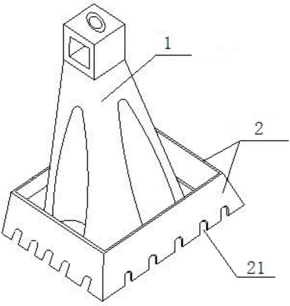
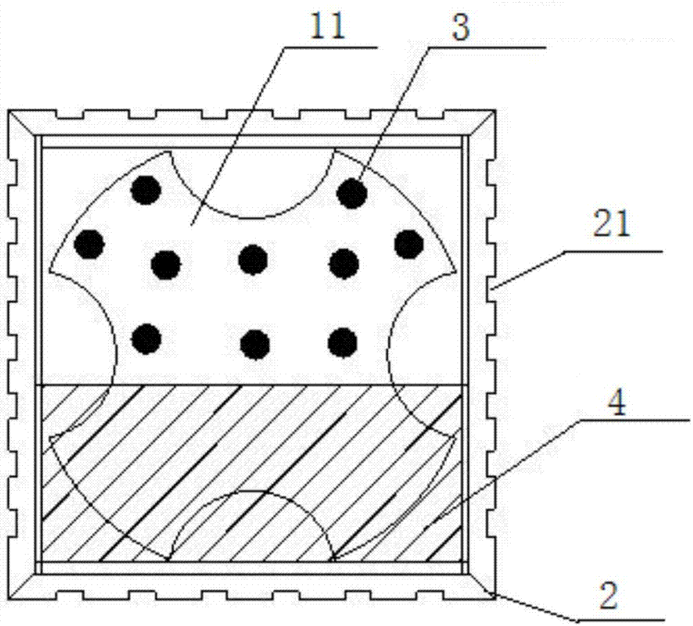
[0028] reference figure 1 , 2 As shown, a rectangular percussion drill bit for the inclined rock trough section of ground connecting wall construction includes a plum blossom percussion drill 1, and also includes a side plate 2, a cone hammer 3, a hammer plate 4, a side plate 2, a cone hammer 3 The hammer plate 4 is preferably made of metal materials, such as steel. The side plate 2 is a flat plate with a serrated edge 21 on one side. The four side plates 2 surround the side of the hammer impact surface 11 of the plum blossom impact drill 1 to form a rectangle. The bottom side of each side plate 2 is a serrated edge 21, and The plane formed by each bottom edge 2 is flush with the hammer impact surface 11 of the quincunx hammer drill 1. The hammer impact surface 11 of the quincunx hammer drill 1 is divided by a line parallel to a certain side plate 2. The impact surface is divided into two halves, one...


PUM

PropertyMeasurementUnit
Bottom diameteraaaaaaaaaa

Abstract

The invention discloses a rectangular impact drill bit for a declined rock groove segment during diaphragm wall construction and a construction method and belongs to the field of diaphragm wall construction. The drill bit comprises a star-shaped impact drill, side plates, conical hammer teeth and a hammer plate, wherein the side plates are flat plates with sawtooth sides, the four side plates form a rectangle around side surfaces of a drill hammer impact surface of the star-shaped impact drill, a plurality of conical hammer teeth are distributed on half impact surface of the drill hammer impact surface of the star-shaped impact drill, and the other half impact surface is covered and fixed with the hammer plate which is a flat plate. The grooving construction method comprises steps as follows: the drill hammer impact surface of the star-shaped impact drill impacts the declined rock groove segment, so that grooves are formed, and groove impacting operation is performed with the side with the conical hammer teeth corresponding to the protruding side of rock in the groove segment and the hammer plate corresponding to the soft soil side in the groove segment. The rectangular impact drill bit and the construction method are suitable for a drill hammer to impact declined rocks in the grooves, so that the grooving dimension and perpendicularity are guaranteed.

Description

Technical field [0001] The invention belongs to the field of ground connecting wall construction, and in particular relates to the construction of a groove section of an inclined rock. Background technique [0002] In the construction of the ground connecting wall, when the groove section of the ground connecting wall encounters a rock structure, the groove forming machine cannot complete the groove forming operation, and the percussion drill must be used to complete the groove forming operation. The general percussion drill bit is generally a plum blossom end face hammer. In the case of complex geological conditions, the elevation of the rock surface in the trough changes greatly, and the uneven force on the end face during the impact of the plum blossom end face hammer is prone to side slip. [0003] The main reason for the side slip of the drill hammer during the impact is the tilt of the rock surface in the groove. When the hammer hits the bottom of the groove, the uneven force...

Claims


Application Information

Patent Timeline
IPC IPC(8): E21B10/36E02D5/18
CPCE21B10/36E02D5/187
Inventor 胡学龙高伟肖植可董君朱耀光黄振刚陈玉平倪海科李敏
Owner KUNMING RAILWAY CONSTR COMPANY OF CHINA RAILWAY NO 8 ENG GRP
Learn More