Step voltage and contact voltage wireless mapping system

A technology of step voltage and contact voltage, which is applied in the signal transmission system, measuring current/voltage, measuring devices, etc., can solve the problems of measurement risk, exceeding the design value, insufficient data density, etc., and avoid cumbersome data processing, Ease of use and improved accuracy

Pending Publication Date: 2017-09-01
STATE GRID HENAN ELECTRIC POWER ELECTRIC POWER SCI RES INST +2
View PDF2 Cites 3 Cited by
  • Summary
  • Abstract
  • Description
  • Claims
  • Application Information

AI Technical Summary

Problems solved by technology

[0002] At present, the measurement of the step voltage and contact voltage of the grounding grid in the power system generally requires at least two people to complete the measurement. One of them holds the voltage measuring device, and the other cooperates with the person stepping on two metal discs as voltage poles. Pick up the metal disk to measure the next point. If you need to record the test data, you need additional configuration personnel. However, in the comprehensive evaluation of the grounding grid of a large substation, there are only hundreds of measurement points for step voltage and touch voltage. The measurement process requires It consumes a lot of human resources and time, and the operation process is not convenient enough, and the processing of a large amount of test data in the later stage is also relatively complicated. Drawing the distribution map of step voltage and contact voltage on the ground surface of the substation grounding grid (or the gradient map of the ground surface potential in the field ) is cumbersome, and the lack of data density leads to inaccurate drawing of the distribution map
[0003] In addition, most of the current power system measures the step voltage and touch voltage of the grounding grid only when the equipment is not put into operation through a small test transformer at low voltage and low current, and then converted to the step voltage and high current under high voltage and high current. Touch voltage, this test is generally not carried out after the equipment is put into operation, but with the successive commissioning of UHVDC power transmission and transformation projects, for example, the measurement of step voltage and touch voltage under single pole operation mode will occur during operation It is also required to carry out, and under such high voltage and high current conditions, it is possible that the value of step voltage and touch voltage will exceed the design value, and the measurement has certain risks. The existing measurement methods have not done this potential danger take precautions

Method used


Image

  • Step voltage and contact voltage wireless mapping system
  • Step voltage and contact voltage wireless mapping system

Examples


Embodiment Construction

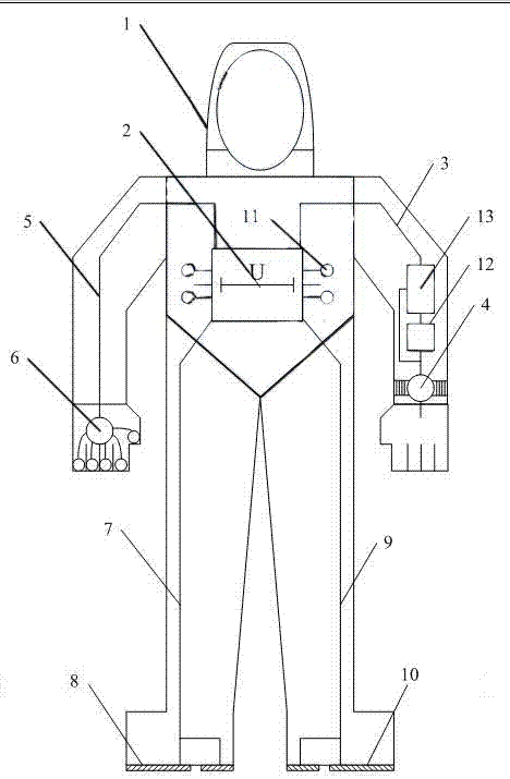
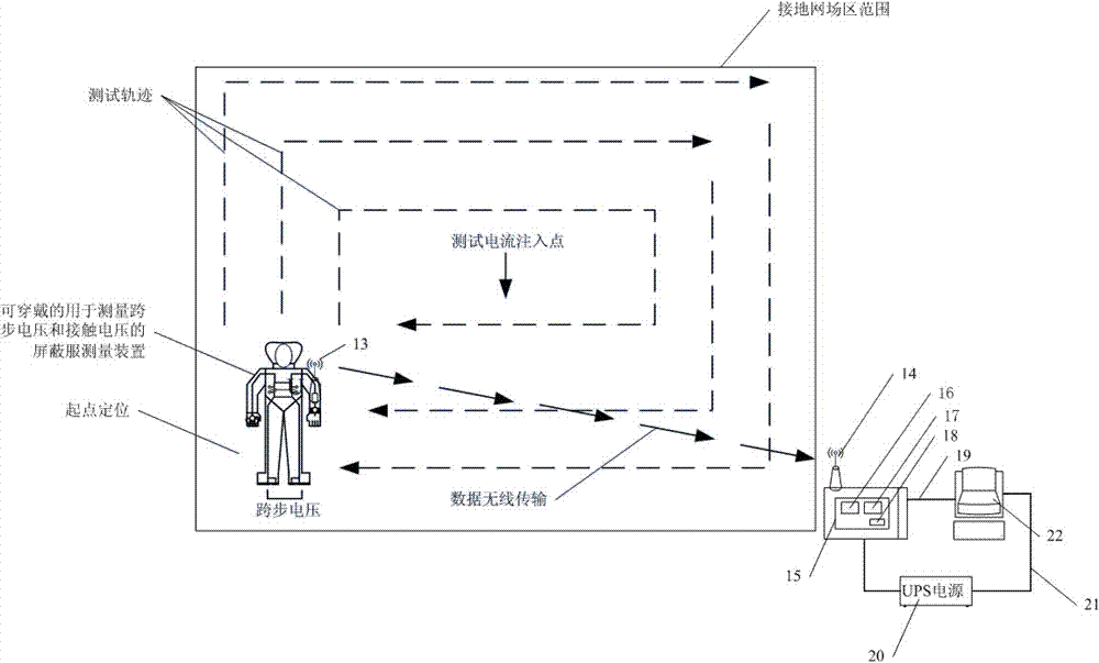
[0017] Such as figure 1 and 2 As shown, the present invention includes a set of wearable shielding clothing measuring device 1 for measuring step voltage and touch voltage, a host 15, a display terminal 22 and a set for power supply to host 15 and display terminal 22 The UPS uninterruptible power supply unit 20; wherein the wearable shielding suit measuring device 1 for measuring step voltage and touch voltage includes a shielding suit body for covering the whole body of the staff and a voltage inter-electrode voltage arranged on the shielding suit Measuring module 2, watch type display terminal 4, contact voltage pole 6, right foot step voltage pole 8, left foot step voltage pole 10, wireless transmission emission module 12, digital-to-analog conversion unit 13, the contact voltage pole 6 It is installed on a glove on the shielding clothing, and by contacting the voltage electrode signal transmission line 5 and the first input terminal of the voltage measurement module 2 bet...


PUM


Abstract

The invention discloses a step voltage and contact voltage wireless mapping system, which comprises a suit of wearable shielding clothes measurement device for measuring step voltage and contact voltage, a host, a display terminal and a uninterrupted power supply (UPS) device. The suit of wearable shielding clothes measurement device for measuring step voltage and contact voltage comprises a shielding clothes body for covering the whole body of a worker and a inter-voltage-electrode voltage measurement module arranged on the shielding clothes body, a watch-type display terminal, a contact voltage electrode, a right-foot step voltage electrode, a left-foot step voltage electrode, a wireless transmission and emission module and a digital-analog conversion unit. The system allows the measurement result thereof to accord with real step voltage and contact voltage situations under actual operating conditions on the premise of ensuring personal safety, and meanwhile, can draw test tracks of test personnel in a grounding grid region and test data of each point synchronously, thereby avoiding complexity of data processing after conventional test, and greatly improving data precision; and the system has a better popularization value.

Description

technical field [0001] The invention relates to the technical field of voltage signal measurement and drawing in a power system, in particular to a wireless surveying and mapping system for step voltage and contact voltage. Background technique [0002] At present, the measurement of the step voltage and contact voltage of the grounding grid in the power system generally requires at least two people to complete the measurement. One of them holds the voltage measuring device, and the other cooperates with the person stepping on two metal discs as voltage poles. Pick up the metal disk to measure the next point. If you need to record the test data, you need additional configuration personnel. However, in the comprehensive evaluation of the grounding grid of a large substation, there are only hundreds of measurement points for step voltage and touch voltage. The measurement process requires It consumes a lot of human resources and time, and the operation process is not convenien...

Claims


Application Information

Patent Timeline
Patent Type & Authority Applications(China)
IPC IPC(8): G01R19/25G08C17/02
CPCG08C17/02G01R19/2503
Inventor 郭磊张劲光寇晓适张科董曼玲丁国君王天王伟王栋
Owner STATE GRID HENAN ELECTRIC POWER ELECTRIC POWER SCI RES INST
Why Eureka
Try Eureka