Flying probe testing system

A technology of flying probe test and flying probe test machine, which is applied in the field of flying probe test system, can solve problems such as slow operation, interference of flying probe test, and low overall efficiency, so as to reduce time and errors, improve test accuracy, and improve work efficiency Effect

Pending Publication Date: 2017-09-01
SHENZHEN MICRONIC TECH
View PDF6 Cites 7 Cited by
  • Summary
  • Abstract
  • Description
  • Claims
  • Application Information

AI Technical Summary

Problems solved by technology

The whole board loading and unloading process is complex, slow operation, time-consuming and labor-intensive, the overall efficiency is low, and it is easy to damage the PCB board due to human error
[0003] The transmission mechanism of the traditional flying probe testing machine is generally installed on a plastic base or a metal base. Due to the huge inertial force generated by the instantaneous start and stop of each transmission mechanism and the rapid movement, the overall body vibration is very frequent. The size of the pads and through-holes of the PCB board is very small, so that the probes cannot accurately touch the pads and through-holes of the PCB board, resulting in other defects such as missed or wrong measurements, so that the test accuracy an

Method used


Image

  • Flying probe testing system
  • Flying probe testing system
  • Flying probe testing system

Examples


Embodiment Construction

[0050] The present invention will be described in detail below in conjunction with the accompanying drawings and specific embodiments.

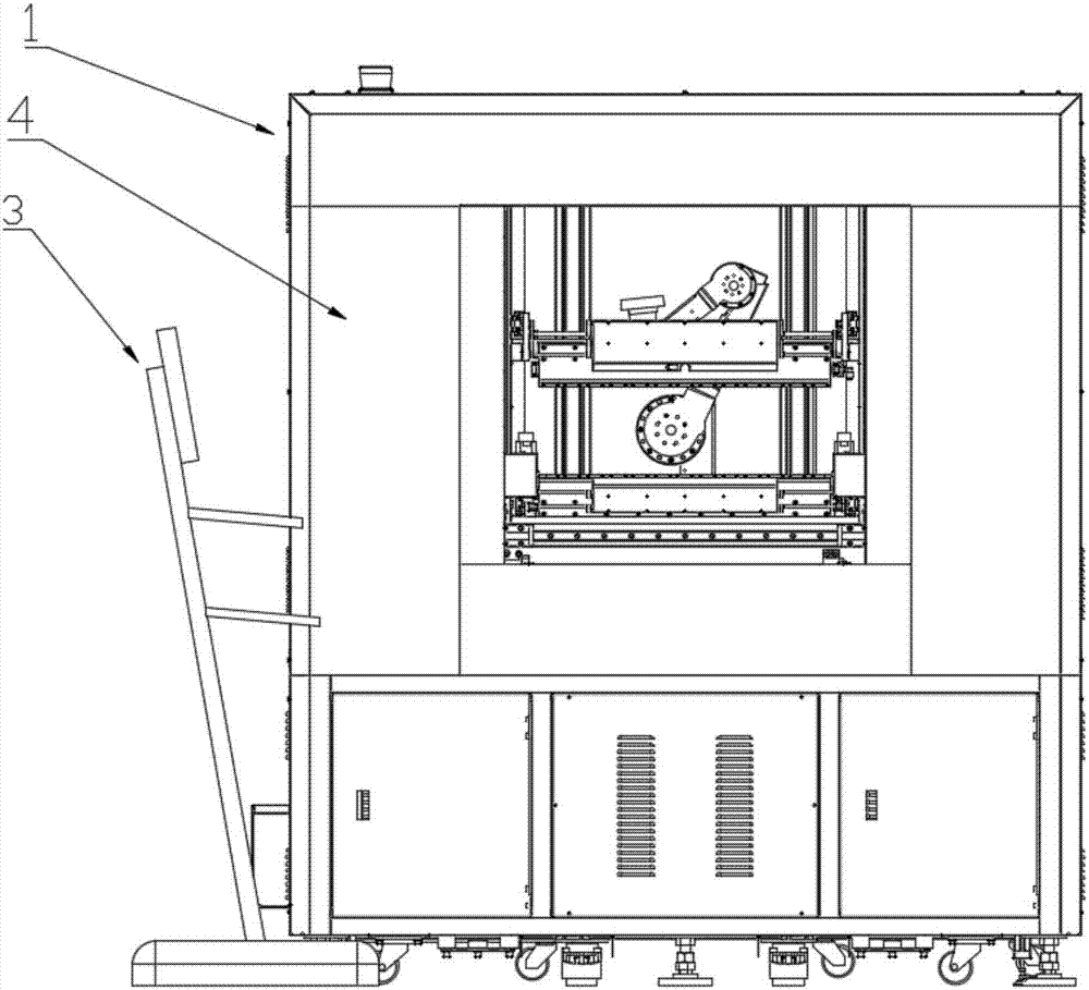
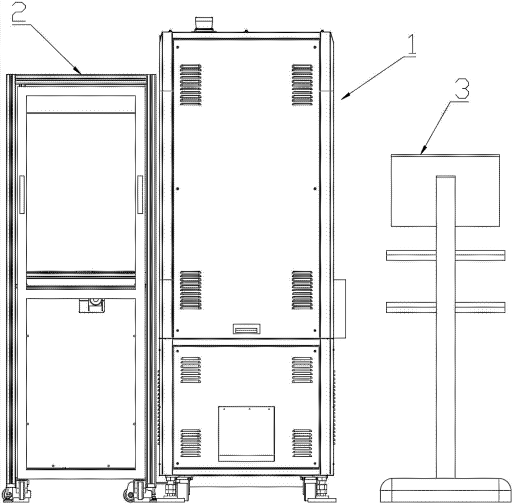
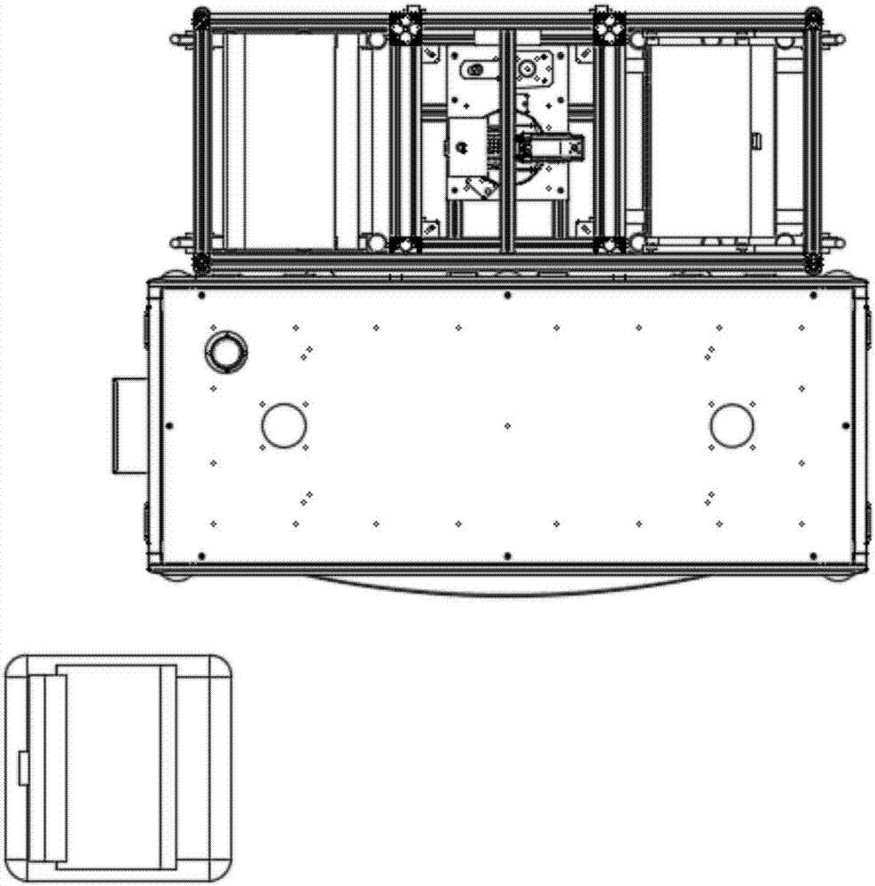
[0051] see Figure 1-Figure 7 , the present invention provides a flying probe testing system, comprising: a flying probe testing machine 1 and an automatic loading and unloading mechanism 2 arranged on one side of the flying probe testing machine 1;

[0052] The flying probe testing machine 1 includes: a base 5, a clamp 6 and a test shaft 7 installed on the base 5, a probe 24 installed on the test shaft 7, and the clamp 6 is an automatic clamping The clamp 6 of the PCB board 45 includes a symmetrically arranged upper clamp and a lower clamp, and the structure of the upper clamp and the lower clamp is the same, and the upper clamp includes: a clamp clamping mechanism and a PCB arranged on the periphery of the clamp clamping mechanism Board positioning mechanism; the clamp clamping mechanism is used to clamp and fix the PCB board 45 , and the ...


PUM


Abstract

The invention discloses a flying probe testing system. The system comprises a flying probe testing machine as well as an automatic feeding and discharging mechanism and a control panel which are arranged on one side of the flying probe testing machine, wherein the flying machine testing machine comprises a base as well as a clamp and a testing shaft which are arranged on the base; the automatic feeding and discharging mechanism comprises a manipulator, a suction cup mounted on the manipulator and a code scanning device. Boards can be automatically supplied to or taken off from the clamp through the manipulator of the automatic feeding and discharging mechanism, and influences of artificial factors on flying probe testing results during manual board feeding and discharging are avoided effectively; the base is a mineral cast base, vibration caused during high-speed operation of the testing shaft can be reduced effectively, a mineral cast machine body formed by pouring mineral materials into a metal frame is adopted, interference of external electromagnetic fields can be reduced, and the testing precision is improved; bar codes or two-dimensional codes on PCBs are scanned and recognized through the code scanning device, time and mistakes made during artificial recognition of models of the PCBs are effectively reduced, and the work efficiency is improved.

Description

technical field [0001] The invention relates to flying probe testing equipment, in particular to a flying probe testing system. Background technique [0002] At present, the vertical flying probe testing machine adopts the method of manually feeding the printed circuit board to place the circuit board to be tested in the upper and lower fixtures of the testing machine. When fixing, it is necessary to operate the operation buttons of the upper and lower fixtures of the testing machine to complete the splinting process. , generally the upper end of the PCB board is fixed by the upper fixture, and the lower end of the PCB board is fixed by the lower fixture; after the inspection is completed, the board is taken out from the upper and lower fixtures of the testing machine by manual removal, and then the qualified board and the unqualified board are separated according to the test results. Place the qualified area and unqualified area of ​​the measured area. The whole board load...

Claims


Application Information

Patent Timeline
IPC IPC(8): G01R31/28
CPCG01R31/2808
Inventor 麦伟东王加勇曾建威康敏优黄达许
Owner SHENZHEN MICRONIC TECH
Why Eureka
Try Eureka