optical module

A technology of optical modules and lasers, which is applied in the field of optical communication systems, can solve problems such as small laser distances and poor heat dissipation of optical modules, and achieve the effects of expanding distances, reducing the probability of heat exchange, and improving heat dissipation capabilities

Active Publication Date: 2020-01-14
HISENSE BROADBAND MULTIMEDIA TECH
View PDF5 Cites 0 Cited by
  • Summary
  • Abstract
  • Description
  • Claims
  • Application Information

AI Technical Summary

Problems solved by technology

[0005] In order to solve the problem of poor heat dissipation of the optical module caused by the small distance between the lasers in the related art, an embodiment of the present invention provides an optical module

Method used


Image

  • optical module
  • optical module
  • optical module

Examples


Embodiment Construction

[0019] In order to make the object, technical solution and advantages of the present invention clearer, the implementation manner of the present invention will be further described in detail below in conjunction with the accompanying drawings.

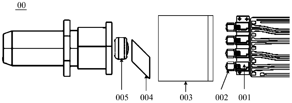
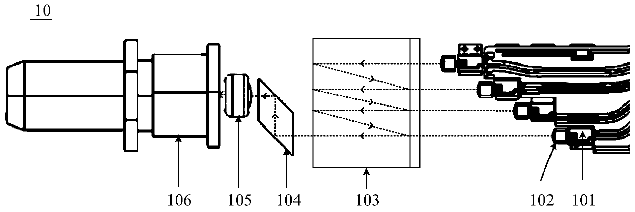
[0020] The embodiment of the present invention provides an optical module 10, such as figure 2 As shown, the optical module 10 may include:

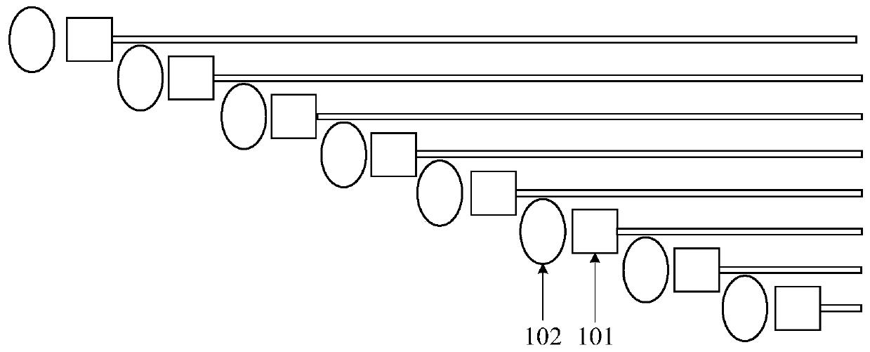
[0021] n lasers 101 , n collimating lenses 102 , wavelength division multiplexer 103 and housing, n is an integer greater than 1, for example: n=4 or n=8.

[0022] n collimating lenses 102 and wavelength division recombiner 103 are fixedly arranged in the housing in turn along the laser emission direction of the laser 101, wherein the n lasers 101 and the n collimating lenses 102 are arranged in one-to-one correspondence, and each of the n lasers 101 The distances from the lasers 101 to the corresponding collimating lenses 102 are equal, and the laser light emitted by each laser 101 is directed...


PUM


Abstract

The invention discloses an optical module, which belongs to the technical field of optical communication systems. The optical module includes: n lasers, n collimating lenses, a wavelength division multiplexer and a housing, wherein n is an integer greater than 1; the n collimating lenses and the wavelength division multiplexing The laser emission direction is fixedly arranged in the housing in turn, wherein the n lasers and the n collimating lenses are arranged in one-to-one correspondence, and the distance from each of the n lasers to the corresponding collimating lens is equal , and the laser light emitted by each laser is directed to the wavelength division multiplexer through the corresponding collimating lens, and the distance between any two adjacent lasers among the n lasers and the light receiving plane of the wavelength division multiplexer is not equal. The invention improves the heat dissipation capability of the optical module. The invention is used to deliver laser light.

Description

technical field [0001] The invention relates to the technical field of optical communication systems, in particular to an optical module. Background technique [0002] In the field of high-speed data communication, optical modules include: lasers, collimating lenses, wavelength division multiplexers, shifting prisms, focusing lenses and adapters, etc. The laser output with a certain power can pass through collimating lenses, wavelength division multiplexers, The displacement prism and focusing lens are injected into the adapter, and then the laser light is guided into the receiving end of the optical fiber through the adapter, and then the laser light is transmitted through the optical fiber. [0003] related technologies, such as figure 1 As shown, the optical module 00 specifically includes a housing (not shown in the figure) and 4 lasers 001, 4 collimating lenses 002, 1 wavelength division multiplexer 003, 1 displacement prism 004 and 1 A focusing lens 005, wherein, 4 l...

Claims


Application Information

Patent Timeline
Patent Type & Authority Patents(China)
IPC IPC(8): G02B6/42H04B10/50
CPCG02B6/4266H04B10/501
Inventor 唐成
Owner HISENSE BROADBAND MULTIMEDIA TECH
Why Eureka
Try Eureka