Flip-flop structure of lighting device and making method thereof

A lighting device and flip-chip technology, applied in the field of lighting, can solve the problems of low yield rate of flip-chip structures

Active Publication Date: 2017-09-05
深圳市尚来特科技有限公司
View PDF6 Cites 5 Cited by
  • Summary
  • Abstract
  • Description
  • Claims
  • Application Information

AI Technical Summary

Problems solved by technology

[0003] Based on this, it is necessary to provide a flip-chip structure of a lighting device with a high yield and a m

Method used


Image

  • Flip-flop structure of lighting device and making method thereof
  • Flip-flop structure of lighting device and making method thereof
  • Flip-flop structure of lighting device and making method thereof

Examples


Embodiment Construction

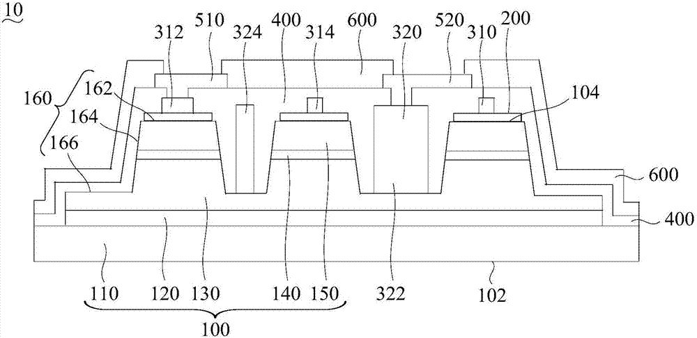
[0052] In order to facilitate the understanding of the present invention, the present invention will be described more fully below with reference to the associated drawings. Preferred embodiments of the invention are shown in the accompanying drawings. However, the present invention can be embodied in many different forms and is not limited to the embodiments described herein. On the contrary, the purpose of providing these embodiments is to make the disclosure of the present invention more thorough and comprehensive.

[0053] It should be noted that when an element is referred to as being “fixed” to another element, it can be directly on the other element or there can also be an intervening element. When an element is referred to as being "connected to" another element, it can be directly connected to the other element or intervening elements may also be present. The terms "inner", "outer", "left", "right" and similar expressions are used herein for the purpose of descripti...


PUM

PropertyMeasurementUnit
Thicknessaaaaaaaaaa
Thicknessaaaaaaaaaa
Thicknessaaaaaaaaaa

Abstract

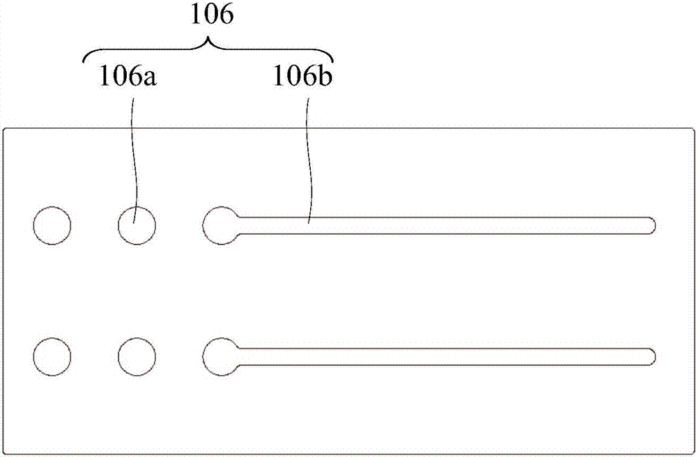
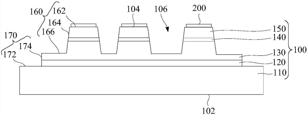
The invention relates to a flip-flop structure of a lighting device and a making method thereof. The flip-chip structure of the lighting device includes a substrate, a buffer layer, an N-type nitride semiconductor layer, an active layer and a P-type nitride semiconductor layer which are laminated. A transparent conductive layer is disposed on the P-type nitride semiconductor layer, the transparent conductive layer is etched to the active layer using the yellow light etching process to expose the N-type nitride semiconductor layer, and a convex mesa is obtained. A P-type contact metal is disposed on the transparent conductive layer, and an N-type contact metal is disposed on the exposed N-type nitride semiconductor layer. A first insulating layer is deposited and etched to expose a portion of the P/N type contact metal. A flip-chip P-type electrode is disposed on the exposed P-type contact metal, and a flip-chip N-type electrode is disposed on the exposed N-type contact metal. A second insulating layer is then deposited and etched to expose a portion of the flip-chip P/N type electrode. In the production of the convex mesa, the accuracy is reduced and the yield is improved by the combination of circular and long strip holes.

Description

technical field [0001] The invention relates to the field of lighting technology, in particular to a flip-chip structure of a lighting device and a manufacturing method thereof. Background technique [0002] In the flip-chip structure of the lighting device, the substrate and the electrode layer are located on both sides of the active layer, and the light excited by the active layer needs to be emitted from the substrate and cannot pass through the electrode layer. A highly reflective material is added to one side of the substrate to reflect light. Commonly used methods include the following two methods: the first method is to directly coat a layer of high-reflectivity metal, such as Ag, Al, etc., between the active layer and the electrode layer. As an ohmic contact layer; the second way is to set the electrode layer as a transparent electrode layer with high transmittance, and then cover a layer of metal with high reflectivity on the transparent electrode layer, such as IT...

Claims


Application Information

Patent Timeline
IPC IPC(8): H01L27/15H01L33/38
CPCH01L27/153H01L33/38H01L33/382H01L2933/0016
Inventor 不公告发明人
Owner 深圳市尚来特科技有限公司
Why Eureka
Try Eureka