Pneumatic fixture for grinding machine processing

A pneumatic and grinding machine technology, applied in the direction of grinding the workpiece support, etc., can solve the problems of affecting the qualified rate of the workpiece, limiting the degree of freedom of rotation, time-consuming and inconvenient, etc., to simplify the cumbersome process of clamping, ensure the overall strength, improve The effect of production efficiency

Active Publication Date: 2019-07-02
宁波友智机械科技有限公司
View PDF11 Cites 0 Cited by
  • Summary
  • Abstract
  • Description
  • Claims
  • Application Information

AI Technical Summary

Problems solved by technology

[0003] At present, chicken heart clamps are generally used as fixtures for shaft processing on grinding machines. The chicken heart clamps are rotated through the chuck installed on the spindle head. Since the chicken heart clamps are tightly clamped on the workpiece, the workpiece will naturally rotate with the chuck, and at the same time limit the Axis rotational degrees of freedom
However, when the workpiece is fixed with the heart clamp, the screw is usually tightened directly, which is time-consuming and inconvenient, especially when the workpiece is produced in batches, it is more cumbersome, which not only affects the pass rate of the workpiece, but also reduces the production efficiency. increase in production costs

Method used


Image

  • Pneumatic fixture for grinding machine processing
  • Pneumatic fixture for grinding machine processing
  • Pneumatic fixture for grinding machine processing

Examples


Embodiment 1

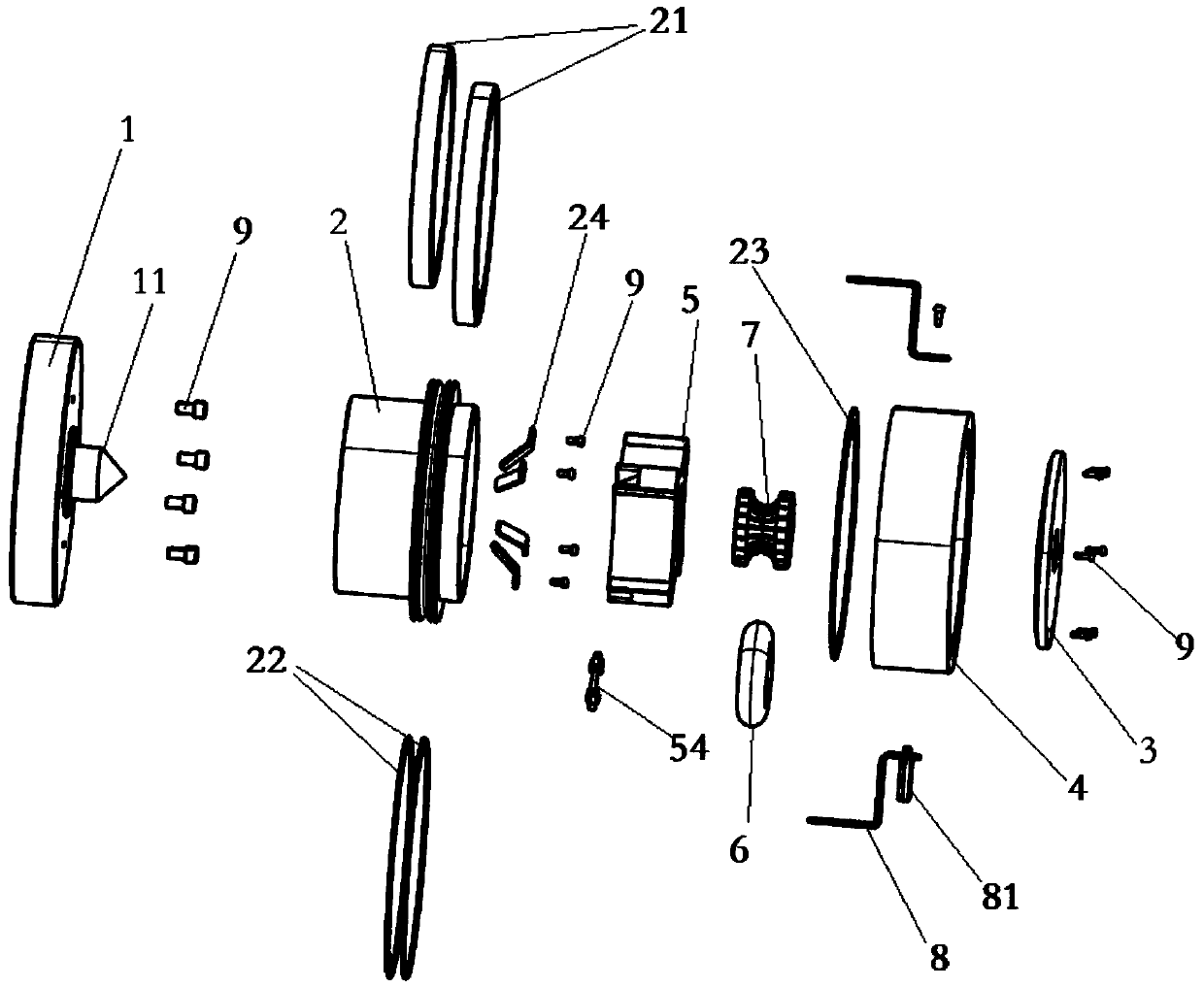
[0040] combine figure 1 As shown, a pneumatic clamp for grinding machine processing includes a rotating shaft plate 1 , a rotating core and a fixed ring 4 , and the rotating core includes a core shell 2 and an end cover 3 . The center of the rotating shaft disk 1 is provided with a front tip 11 for positioning the workpiece. Both the end faces of the movement shell 2 and the end cover 3 are provided with circular through holes for the passage of workpieces such as shafts and rods. The rotating shaft of described rotating shaft disc 1 and processing grinder, the end face of movement shell 2 and rotating shaft disc 1, end cover 3 and movement housing 2 are all connected by screw 9, when the rotating shaft of grinding machine rotates, rotating shaft disc 1 and Turn the movement to follow the rotation.

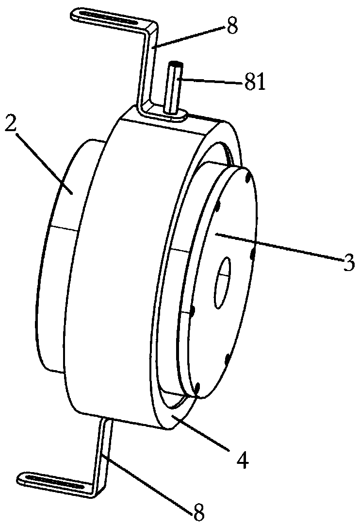
[0041] combine figure 2 As shown, the fixed ring 4 is fixedly connected with the main body of the grinder through the fixed bracket 8, and the fixed ring 4 is fixed in positio...

Embodiment 2

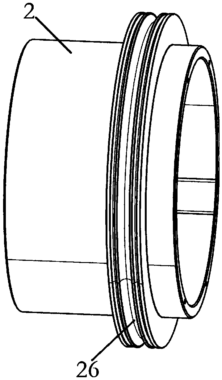
[0046] On the basis of the above-mentioned embodiments, this embodiment combines Figure 5 As shown, a spring leaf 24 is installed on the quarter point of the movement cavity 25 . combine Image 6 As shown, the surface of the airbag frame 5 is provided with a spring plate installation groove 52 corresponding to the spring plate 24 . The air bag frame 5 is installed in the movement cavity 25, and the leaf spring 24 enters the spring leaf mounting groove 52. There is a gap between the four corners of the air bag frame 5 and the inner wall of the movement cavity 25, and the air bag frame 5 can compress the spring leaf to carry out small displacement and turn.

[0047]The through holes of each part of the fixture are concentric with the front top 11, and the workpiece is automatically centered during installation, and when the four sides of the airbag frame 6 are under uneven force, the spring leaf 24 will be compressed to achieve a small position and rotation, and automatic dev...

Embodiment 3

[0049] On the basis of the above-mentioned embodiments, this embodiment combines Image 6 with Figure 7 As shown, the airbag frame 5 is cross-shaped, and a through hole is arranged in the middle thereof. The airbag frame 5 is provided with an elastic ring installation cavity 51 for positioning the elastic ring 7 . In addition, an airbag groove 53 is provided in the middle of the side wall of the elastic ring installation cavity 51 for positioning the airbag 6 . The ends of the four protruding sides of the airbag frame 5 are provided with spring mounting grooves 52 . The cross-shaped structure improves the force sensitivity of the airbag frame 5 and improves the centering accuracy.


PUM


Abstract

The invention discloses a pneumatic type clamp for grinding machine machining. The pneumatic type clamp comprises a rotating shaft disk, a rotating machine core and a fixing ring, wherein the rotating shaft disk is connected with a grinding machine rotating shaft, and a front centre is arranged in the center of the rotating shaft disk; the rotating machine core comprises a machine core shell and an end cover, a machine core cavity is formed between the machine core shell and the end cover, the machine core shell is connected with the rotating shaft disk, the machine core cavity is internally provided with an air bag frame, an air bag and an elastic ring all of which are sequentially arranged from exterior to interior, an annular vent groove is formed in the outer wall of the machine core shell, and the vent groove communicates with the air bag through an air pipe arranged in the air bag frame; and the fixing ring is connected with the machine core shell through bearings, air inlet holes are formed in the surface of the fixing ring and communicate with the vent groove, and a gas channel is formed between the fixing ring and the vent groove. The clamp is ingenious in design, the air bag can be inflated so that the elastic ring can transform, pressure is exerted to clamp a workpiece tightly, automatic operation of workpiece clamping and dismounting can be achieved, complex working procedures of clamping in a traditional machining process are simplified, and the production efficiency is improved.

Description

technical field [0001] The invention relates to the technical field of grinding machine processing fixture equipment, in particular to a pneumatic clamp for grinding machine processing. Background technique [0002] Rod shaft workpieces are commonly used parts in the machinery industry and play a vital role in the machinery industry, such as eccentric shafts in compressors, transmission shafts in reducers, shaft parts in automobiles, etc. These shaft parts need to be cut on the grinding machine, and they need to be positioned and tightened by fixtures during processing. [0003] At present, chicken heart clamps are generally used as fixtures for shaft processing on grinding machines. The chicken heart clamps are rotated through the chuck installed on the spindle head. Since the chicken heart clamps are tightly clamped on the workpiece, the workpiece will naturally rotate with the chuck, and at the same time limit the Axis rotational degrees of freedom. However, when the wo...

Claims


Application Information

Patent Timeline
Patent Type & Authority Patents(China)
IPC IPC(8): B24B41/06
CPCB24B41/06
Inventor 陈友展
Owner 宁波友智机械科技有限公司
Why Eureka
Try Eureka