Wood board loading and unloading lifting assembly

A technology of loading and boarding, which is applied in the field of board loading and unloading lifting assembly, can solve the problems of high physical consumption of feeding personnel, low feeding efficiency, and decline in product quality, so as to achieve efficiency improvement, high work efficiency, and manpower The effect of low consumption

Active Publication Date: 2017-09-08
LIUZHOU VOCATIONAL & TECHN COLLEGE
View PDF7 Cites 16 Cited by
  • Summary
  • Abstract
  • Description
  • Claims
  • Application Information

AI Technical Summary

Problems solved by technology

In the process of loading and unloading the hot press, two methods are currently used: 1. Manual loading and unloading: the efficiency is extremely low, and only one side of the board and stickers can be pressed into the hot press at a time, which will cause the same surface to be covered. Two times of hot pressing, the product quality is reduced, and the energy consumption is high; and the feeding personnel consume a lot of physical strength and low efficiency; 2. Belt conveying equipment: the feeding efficiency is not high, the structure is backward, and only the hot press with low output can be fed. Only one side can be pressed at a time, and the conveying accuracy is low

Method used


Image

  • Wood board loading and unloading lifting assembly
  • Wood board loading and unloading lifting assembly
  • Wood board loading and unloading lifting assembly

Examples


Embodiment 1

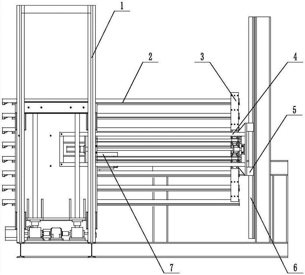
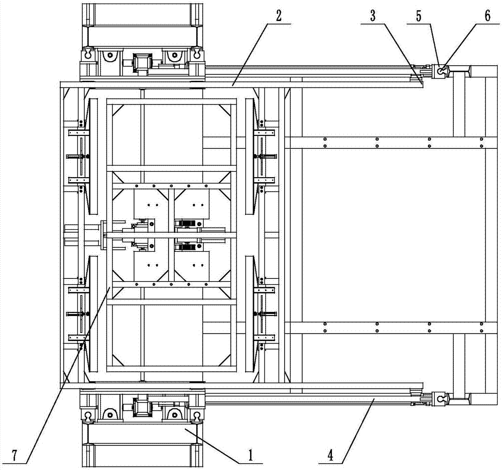
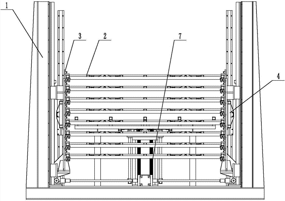
[0043] Such as Figure 1-6 Shown, a kind of plank loading and unloading lifting assembly, it comprises elevating mechanism 1, jacking mechanism 7, pushing mechanism 8 and 8 supporting mechanisms 2; Elevating mechanism 1 comprises elevating mechanism base 101, and elevating mechanism base 101 A lifting mechanism support 105 is respectively established on the front end left and right, and the lifting mechanism support 105 is provided with a lifting component 106. The front end of the lifting mechanism base 101 is also provided with a lifting component driver 102. Part 102 drives the lifting part 106 to move up and down; the rear end of the lifting mechanism base 101 is respectively provided with a limit column 104, and the adjacent side of the limit column 104 is provided with a vertical linear guide rail IV6; the front ends of the eight supporting mechanisms 2 are located on The top of the jacking mechanism 7 is located between the lifting mechanism brackets 105 and is connecte...

Embodiment 2

[0045] Such as Figure 1-6 , 13-16, on the basis of Embodiment 1, the jacking mechanism 7 also includes a linear guideway V704, a linear bearing 708, a linear guideway V connecting rod 709 and a jacking mechanism rack 705, a linear guideway V704 and a linear bearing 708 Flexible connection, the linear bearing 708 is located on the support pad 707, one end of the linear guide V 704 is connected with the lifting platform 702, and the other end passes through the support pad 707 to connect with the linear guide V connecting rod 709; the jacking mechanism rack 705 is located on In the jacking mechanism frame 706 , one end passes through the support pad 707 and is connected to the lifting platform 702 , and the other end is connected to the bottom plate of the jacking mechanism frame 706 , and the lifting platform driver 703 is rollingly connected to the jacking mechanism rack 705 . Lifting table driver 703 includes servo motor gear 7031, reducer 7032 and jacking mechanism servo mo...

Embodiment 3

[0047] Such as Figure 1-6 As shown, on the basis of Embodiment 1, the lifting part 106 of the lifting mechanism 1 includes a lifting riser 1061 and several supporting mechanism supporting plates 1062, and the supporting mechanism supporting plates 1062 are evenly spaced and arranged on the front of the lifting vertical plate 1061 The lifting part driver 102 includes steering gear 1021, screw lifter 1022, lifting mechanism screw mandrel 1023, transmission rod 1024, lifting mechanism servo motor 1025 and belt seat bearing 1026, and lifting mechanism servo motor 1025 and transmission rod 1024 are located at the lifting mechanism Between the brackets 105, the steering gear 1021 and the screw lifter 1022 are arranged below the lifting mechanism bracket 105, and the bearing with seat 1026 is arranged on the back side of the lifting vertical plate 1061; the lifting mechanism servo motor 1025 is connected with the steering gear 1021 through a transmission rod 1024, and the steering ge...


PUM


Abstract

The invention discloses a wood board loading and unloading lifting assembly which comprises a lifting mechanism (1), a jacking mechanism (7), a push mechanism (4) and a plurality of bearing and connecting mechanisms (2). The wood board loading and unloading lifting assembly has the advantages that working efficiency is high, energy consumption is reduced, manpower is saved, conveying precision is high, and a hot press can conduct hot pressing on the two faces simultaneously.

Description

technical field [0001] The invention belongs to the field of automatic feeding and unloading, and in particular relates to a wooden board loading and unloading lifting assembly. Background technique [0002] In the wood processing and manufacturing industry, especially the hot-pressed veneer production industry of wood boards, the degree of automation of equipment is relatively backward, and it is basically manual. In the process of loading and unloading the hot press, two methods are currently used: 1. Manual loading and unloading: the efficiency is extremely low, and only one side of the board and stickers can be pressed into the hot press at a time, which will cause the same surface to be covered. Two times of hot pressing, the product quality is reduced, and the energy consumption is high; and the feeding personnel consume a lot of physical strength and low efficiency; 2. Belt conveying equipment: the feeding efficiency is not high, the structure is backward, and only th...

Claims


Application Information

Patent Timeline
Patent Type & Authority Applications(China)
IPC IPC(8): B27D1/08B27D3/00B32B37/10B32B37/06B65G47/74B65G47/82
CPCB27D1/083B27D3/00B32B37/06B32B37/10B65G47/74B65G47/82
Inventor 吴兆辉陈晖罗喻允
Owner LIUZHOU VOCATIONAL & TECHN COLLEGE
Why Eureka
Try Eureka